
BriHyNergy Commercializes 15MW PEM Electrolyzer System: A DeepDive into MegawattScale Electrochemical Engineering, BOP Optimization, and LCOH Dynamics
Engineering Insight: The global energy transition has reached a crucial inflection point where industrial decarbonization demands deep, scalable, and highly dynamic electr…
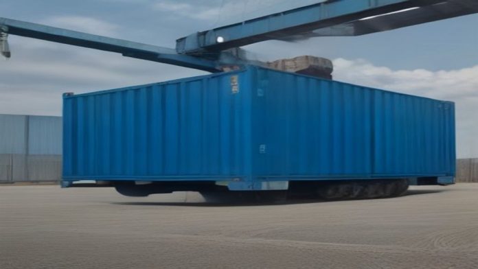
The global energy transition has reached a crucial inflection point where industrial decarbonization demands deep, scalable, and highly dynamic electrification technologies. Marking a substantial commercial milestone in utilityscale green hydrogen production, clean energy technology provider BriHyNergy has officially completed the factory acceptance testing and shipment of its 15megawatt (MW) Proton Exchange Membrane (PEM) hydrogen generation platform. Designed to supply highpurity hydrogen for heavy industrial, chemical feedstock, and energy storage applications, this deployment underscores a major shift from earlystage pilot systems toward optimized, industrialscale multimegawatt modular architectures.
As hardtoabate sectors such as green steelmaking (direct reduced iron), zeroemission ammonia synthesis, and refining operations demand steady, highvolume flows of renewable hydrogen, engineering teams face the operational challenge of matching static industrial chemical processes with highly intermittent renewable energy assets. The deployment of BriHyNergy’s 15MW PEM system demonstrates the maturing capability of advanced polymer electrolyte systems to handle fast dynamic response rates, operate under high current densities, and maintain strict output purity standards. Below, Avoltium’s engineering editorial team provides an exhaustive technical analysis of the electrochemistry, Balance of Plant (BOP) integration, power electronics, economic impacts, and structural market drivers behind this milestone delivery.
Technical Breakdown: Electrochemistry, Stack Design, and Balance of Plant Integration
The core innovation of the 15MW BriHyNergy platform resides within its modularized PEM electrolyzer stack assembly. Unlike legacy liquid alkaline systems, Proton Exchange Membrane electrochemistry relies on a solid polymer electrolyte—typically a perfluorosulfonic acid (PFSA) fluoropolymer membrane—which facilitates rapid proton transport while acting as a robust physical barrier to gas crossover. This fundamental structural difference enables superior operational flexibility and significantly higher differential pressure capabilities.
1. Stack Architecture and Electrochemical Performance
The 15MW configuration utilizes highperformance cell stacks designed to operate at elevated current densities, typically ranging between 2.0 A/cm² and 3.0 A/cm². Operating at these densities drastically minimizes the required physical footprint per megawatt of capacity when compared to traditional Alkaline Electrolysis (AWE) units. Key parameters governing the electrochemical core include:
- Catalyst Thrashing and Thrifting: The anode side, subject to the highly corrosive Oxygen Evolution Reaction (OER) and acidic operating environment, utilizes lowloading Iridium Oxide (IrO₂) catalysts supported on corrosionresistant titanium structures. The cathode side, driving the Hydrogen Evolution Reaction (HER), utilizes Platinum supported on carbon (Pt/C). Recent engineering advancements focused on thrifting noble metal content have lowered iridium loadings toward <0.4 g/kW, critical for scaling stack production against global PGM supply limitations.
- Porous Transport Layers (PTL) and Bipolar Plates: To survive high oxidative potentials at the anode, the system incorporates sintered titanium fiber felt PTLs coated with thin, conductive protective layers (such as Platinum, Gold, or Titanium Nitride). These coatings mitigate the formation of resistive titanium oxide layers, preserving longterm electrical contact resistance (ICR) metrics across tens of thousands of operating hours.
- Differential Pressure Operation: The stack is engineered to deliver compressed green hydrogen directly at 30 to 50 bar without requiring an initial mechanical booster compressor. Generating hydrogen directly at pressure reduces parasitic electrical loads, lowers total system footprint, and simplifies downstream conditioning loops.
2. Balance of Plant (BOP) Fluidics and Conditioning Architectures
A 15MW PEM electrolyzer system cannot be evaluated on stack metrics alone; the operational efficiency, safety, and reliability are largely dictated by the external Balance of Plant (BOP). At a 15MW nominal input rating, the system consumes approximately 2.7 to 3.0 metric tons of ultrapure demineralized water per hour (based on the stoichiometric minimum of 9 kg H₂O per kg H₂, plus process blowdown and purges).
- Feedwater Demineralization Loop: Raw water must undergo multistage reverse osmosis (RO) followed by continuous electrodeionization (EDI) to achieve ASTM D5127 Type I water quality standards (electrical conductivity <0.1 µS/cm). Any ionic contaminants (such as Fe, Cu, or Cl ions) entering the stack would poison the PFSA membrane and cause irreversible degradation of active catalyst sites.
- GasLiquid Separation and DeOXo Purification: Raw wet hydrogen exiting the cathode manifold at high pressure enters a primary gasliquid separator to drop out entrained process water. The saturated gas is then routed through a catalytic DeOXo unit (utilizing a palladiumbased catalyst bed) where trace oxygen crossover is reactively combined with hydrogen to form water vapor. Subsequently, a dualbed temperature swing adsorption (TSA) or pressure swing adsorption (PSA) dryer removes residual moisture, delivering ISO 14687 Grade D compliant fuel cellgrade hydrogen (>99.999% purity) with oxygen concentrations below 1 ppmv and moisture below 5 ppmv.
- Thermal Management and Heat Recovery: Approximately 25% to 30% of the total electrical energy input is converted into waste heat due to activation, ohmic, and concentration overpotentials. The 15MW skid utilizes closed-loop deionized water cooling loops paired with titanium plate heat exchangers. Advanced plant architectures integrate this lowgrade waste heat (60°C to 70°C) into district heating networks or low-temperature industrial thermal processes, raising total system energy utilization efficiency beyond 80%.
3. Power Electronics, Rectification, and Grid Interfacing
Connecting a 15MW electrochemical load directly to variable renewable power sources (wind and solar PV) requires specialized power electronics. The system employs active frontend (AFE) insulatedgate bipolar transistor (IGBT) rectifiers designed to deliver smooth, highefficiency direct current (DC) with exceptionally low current ripple (<2%). High DC ripple induces thermal stress on catalyst layers and accelerates membrane degradation.
“Furthermore, the power supply is tuned to meet stringent grid code requirements, maintaining a high power factor (>0.98)…”
Furthermore, the power supply is tuned to meet stringent grid code requirements, maintaining a high power factor (>0.98) and keeping Total Harmonic Distortion (THD) under 3% at the point of common coupling (PCC). The dynamic ramp capability of the PEM platform enables millisecondtosecond response times, allowing the system to participate directly in grid frequency regulation markets, such as Frequency Containment Reserve (FCR) and automatic Frequency Restoration Reserve (aFRR).
Comparative Analysis: PEM vs. ALK vs. SOEC
To contextualize BriHyNergy’s 15MW PEM deployment within the broader electrolysis landscape, the following technical matrix outlines key differences among the primary electrolyzer archetypes:
| Technology Metric | Proton Exchange Membrane (PEM) | Alkaline Electrolysis (AWE) | Solid Oxide Electrolysis (SOEC) |
|---|---|---|---|
| Operating Temperature | 50°C 80°C | 60°C 90°C | 650°C 850°C |
| Operating Pressure | 30 50+ bar (Differential) | 1 30 bar (Atmospheric/Slight Pressurized) | 1 10 bar |
| Current Density | 1.5 3.0 A/cm² | 0.2 0.6 A/cm² | 0.3 1.0 A/cm² |
| Dynamic Load Range | 0% 120% nominal power | 15% 100% nominal power | 30% 100% (Thermal limits match baseline) |
| Cold Start Duration | < 15 minutes | 1 4 hours | Hours to Days (Requires thermal ramp) |
| Specific Energy Consumption | 50 60 kWh/kg H₂ (System Level) | 50 65 kWh/kg H₂ (System Level) | 38 45 kWh/kg H₂ (Thermally Integrated) |
| System Footprint | Compact / High Power Density | Large / Extensive Piping | Moderate (Requires insulation blocks) |
Market & Economic Impact: LCOH Sensitivities and Industrial Scaling
The operational commissioning of a 15MW PEM plant has profound economic implications for calculating the Levelized Cost of Hydrogen (LCOH). In current green hydrogen economics, LCOH is predominantly governed by two metrics: capital expenditure (CAPEX) amortized over system lifespan, and operating expenditure (OPEX), which is heavily dominated by electricity costs (accounting for 70% to 80% of total LCOH).
At a systemlevel efficiency of roughly 52 kWh per kilogram of H₂, a 15MW electrolyzer operating at full capacity can produce approximately 288 kg of highpurity hydrogen per hour, translating to roughly 6.9 metric tons of H₂ per day. The economic dynamics of this scale introduce clear optimization pathways:
- CAPEX Reduction via Skid Modularization: Moving from bespoke, fielderected 1MW5MW systems to factoryassembled, standardized 15MW modular skids drastically decreases engineering, procurement, and construction (EPC) lead times and field labor costs. Standardized skid manufacturing yields volume learning curves that bring down stack and BOP manufacturing expenditures toward targets under 600/kW.
- Dynamic Arbitrage and Flexible Renewable Capture: Because the 15MW PEM platform can ramp from minimum turndown to full overload in seconds, operators can strategically run the electrolyzer during periods of negative or ultralow wholesale electricity prices. By pairing the stack with real-time dynamic pricing algorithms, the effective levelized cost of electricity fed to the stack is reduced, driving down total LCOH toward the 2.003.00/kg target necessary to compete with unabated steam methane reforming (SMR).
- Regulatory Compliance and Subsidy Qualification: Large-scale deployments in key markets must navigate complex regulatory standards. In the European Union, compliance with the Renewable Energy Directive III (RED III) Delegated Acts demands strict adherence to additionality, temporal correlation (moving toward hourly matching by 2030), and geographical correlation for Renewable Fuels of NonBiological Origin (RFNBO). In the United States, achieving the full 3.00/kg clean hydrogen production tax credit under Section 45V of the Inflation Reduction Act (IRA) relies heavily on matching production with hourly clean power generation—a requirement where fastresponding PEM technology holds a distinct operational advantage over slower alkaline systems.
Future Outlook: Building Blocks for GigawattScale Green Hydrogen Hubs
The delivery of BriHyNergy’s 15MW PEM system serves as a practical baseline for the next phase of the hydrogen economy: transition from multimegawatt demonstration projects to multihundredmegawatt and gigawattscale production hubs. Singletrain 15MW modular units serve as standardized, repeatable “building blocks” for large-scale facility design.
As project developers design facilities requiring 100MW to 500MW of total electrolyzer capacity, stacking multiple standardized 15MW or 20MW blocks offers major plant architecture advantages:
- Redundancy and Availability: Multiblock plant layouts allow individual 15MW skids to undergo routine maintenance, catalyst inspection, or water treatment flushing without shutting down the entire facility, maintaining baseline hydrogen production for offtakers.
- Shared BOP Efficiencies: While each 15MW block maintains independent stack safety and localized fluid control, plants can utilize centralized raw water pretreatment, bulk hydrogen storage manifolds, and highvoltage substation switchgear, capturing significant scale economies.
- Advanced Materials and Degradation Mitigation: Next-generation developments will focus on reducing stack degradation rates below 0.25% per 1,000 hours, extending operational stack lifetimes beyond 80,000 hours. Research into hydrocarbonbased membranes, lowiridium catalyst coated membranes (CCMs), and additivemanufactured flow field plates will further compress CAPEX while improving thermal efficiency.
In summary, BriHyNergy’s shipment of its 15MW PEM system represents far more than an individual equipment sale. It highlights the technological maturation of proton exchange membrane electrolysis as a robust, dynamic, and industrially viable solution capable of anchoring large-scale decarbonization projects worldwide. As manufacturing supply chains scale up and power grids integrate higher ratios of variable renewables, highcapacity modular PEM architectures will remain a vital pillar in achieving global netzero emissions targets.