

I am Arun, Chief Engineer at Avoltium. In the rapidly evolving landscape of green hydrogen production, the modern water Electrolyzer stands as the primary technological bridge between variable renewable energy sources and heavy industry decarbonization. While Proton Exchange Membrane (PEM) electrolysis has long been recognized for its rapid dynamic response, high power density, and ability to operate under high differential pressures, conventional stack designs face strict thermodynamic and economic limits. To push operating current densities from historical norms of 1.52.0 A/cm² toward>3.5 A/cm² without suffering severe efficiency dropoffs, system architects must address the fundamental overpotentials that govern the electrochemical cell: activation, ohmic, and mass transport (concentration) losses.
Thermodynamic Foundations and Voltage Losses in PEM Stacks
The standard enthalpy change (Delta H°) for water splitting under standard temperature and pressure (STP) conditions is 285.8 kJ/mol (based on the Higher Heating Value, HHV), corresponding to a thermoneutral voltage (Vtn) of 1.48 V. The reversible cell voltage (Vrev), derived from the Gibbs free energy change (Delta G° = 237.2 kJ/mol), is 1.23 V. At cell voltages between 1.23 V and 1.48 V, the reaction is endothermic and requires external heat input. Above 1.48 V, the cell operates exothermically, generating waste heat that must be continuously rejected via thermal management systems.
The real operating cell voltage (Vcell) is expressed as the sum of thermodynamic and loss terms:
Vcell = Vrev + ηact,a + |ηact,c| + ηohm + ηtrans
Where ηact,a and ηact,c represent the activation overpotentials at the anode (Oxygen Evolution Reaction, OER) and cathode (Hydrogen Evolution Reaction, HER), ηohm denotes total internal ohmic losses (membrane, porous transport layers, bipolar plates, interfacial contact resistance), and ηtrans is the concentration overpotential driven by mass transport limitations at elevated current densities.
“Minimizing internal ohmic losses through ultrathin, mechanically reinforced Perfluorosulfonic Acid (PFSA) membranes is the single most effective lever for maintaining stack efficiencies above 80% HHV at elevated current densities.”
Advanced MEA Topologies and Catalyst Loading Reduction
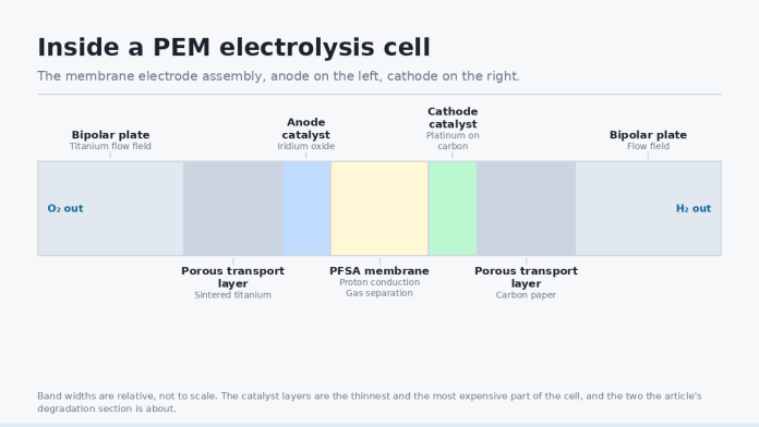
The Membrane Electrode Assembly (MEA) is the core electrochemical engine of the Electrolyzer. Historical PEM designs relied heavily on thick membranes (e.g., Nafion 117, ~183 µm thickness) to limit hydrogen gas crossover under differential pressure. However, thick membranes introduce prohibitive ohmic resistance (R_Omega), causing significant voltage runup as current density scales.
UltraThin Reinforced Membranes
Modern cell architectures utilize expanded polytetrafluoroethylene (ePTFE) reinforced PFSA membranes with thicknesses ranging between 15 µm and 30 µm. The ePTFE matrix provides mechanical structural integrity, preventing yield deformation and swelling under high differential pressure (e.g., 3080 bar H2 vs. atmospheric O2). To address the increased rate of gas crossover (permeation of H2 molecules across the thin ionomer into the O2 stream), next-generation membranes incorporate platinum nanorecombination catalysts embedded directly within the membrane bulk. These catalytic sites convert crossing H2 and O2 safely back into water before explosive limits (4% H2 in O2) are approached.
LowLoading IrO₂ and Nanostructured Catalyst Interfaces
The anode side presents the kinetic bottleneck of water electrolysis due to the sluggish fourelectron transfer mechanism of the OER. Traditional anodes rely on high iridium dioxide (IrO2) loadings (2.03.0 mg Ir/cm²). To reduce capital costs without inducing catalytic passivation, Avoltium’s research focuses on coreshell structures and iridiumtitanium mixed metal oxides (MMO). By dispersing subnanometer IrO2 domains onto conductive, corrosionresistant titanium oxide or antimonydoped tin oxide (ATO) supports, catalyst loadings are reduced to <0.4 mg Ir/cm² while preserving electrochemically active surface area (EASA) and Tafel slopes below 60 mV/decade.
Fluid Dynamics, Porous Transport Layers, and Flow Field Geometries
As operating current densities exceed 3.0 A/cm², local gas bubble accumulation within the catalyst layer and Porous Transport Layer (PTL) severely restricts liquid water access to active catalytic sites. This transition marks the onset of mass transport overpotential (ηtrans).
GradientPorosity Titanium PTLs
Anode PTLs must withstand high anodic potentials (>1.7 V vs. RHE) in an oxidizing environment, ruling out carbonbased materials. Sintered titanium powder or titanium felt PTLs are standard. Nextgen architectures implement duallayer, gradientporosity designs featuring a Fine Microporous Layer (MPL) adjacent to the catalyst layer (pore diameter 510 µm) and a coarse macroporous backing layer (pore diameter 3050 µm) facing the flow field channel. This structural gradient establishes distinct microcapillary pathways for liquid water feed and gaseous oxygen egress, preventing localized twophase liquidgas starvation.
Interfacial Contact Resistance (ICR) Mitigation
To prevent passivating TiO2 layer formation on titanium PTLs and Bipolar Plates (BPPs)—which rapidly increases ohmic contact resistance over time—thin, highly conductive protective coatings are applied via Physical Vapor Deposition (PVD) or Atomic Layer Deposition (ALD). Platinumiridium alloy coatings or titanium nitride (TiN) layers keep the Interfacial Contact Resistance (ICR) below 5 mΩ·cm² under standard stack clamping pressures (1.52.5 MPa).
Upstream Feedstock Quality and Water Treatment Integration
A critical, often underestimated component of highefficiency Electrolyzer plant design is the balanceofplant (BoP) water purification loop. The Perfluorosulfonic Acid ionomer within the MEA relies on sulfonic acid groups (SO3 H+) to facilitate rapid proton hopping via the Grotthuss mechanism. The presence of trace chemical impurities in the feed water rapidly deteriorates cell performance.
“Chemical contamination of the membrane ionomer by trace multivalent cations causes rapid, irreversible ionic resistance spikes and triggers hydrogen peroxide radical generation that degrades the polymer backbone.”
Poisoning Mechanisms
Multivalent Cations (Ca2+, Mg2+, Fe2+/3+, Cu2+) possess a higher affinity for the -SO3 binding sites than protons (H+). When present in the feedwater, these cations displace protons within the ionomer, dramatically reducing ionic conductivity and driving up ηohm. Furthermore, transition metal ions such as Fe2+ and Cu2+ act as active catalysts for Fenton reactions, decomposing trace hydrogen peroxide (H2O2) sideproducts into aggressive hydroxyl (·OH) and hydroperoxyl (·OOH) radicals. These radicals attack the carboxylic and sulfonic endgroups of the polymer matrix, causing structural thinning, fluoride emission, and eventual membrane breach.
Integrated Water Treatment Plant Architecture
To assure operational lifetimes exceeding 80,000 hours, modern green hydrogen facilities integrate a multistage, closed-loop Water Treatment architecture designed to meet ASTM Type I ultrapure water (UPW) specifications:
- Prefiltration and Reverse Osmosis (RO): Multimedia filtration followed by doublepass RO removes suspended solids, dissolved organics, and the majority of monovalent and divalent ions.
- Continuous Electrodeionization (CEDI): An applied electric field drives residual ions through ionexchange membranes, continuously polishing the water stream without requiring chemical regenerants.
- Ultraviolet (UV) Oxidation & Degasification: UV reactors operating at 185 nm destroy residual Total Organic Carbon (TOC), while membrane contactor modules strip dissolved oxygen and carbon dioxide gases down to subppb levels.
- Polishing MixedBed Resin Loops: A dedicated recirculating ultrapure water loop maintains feedstock electrical resistivity strictly at 18.2 MΩ·cm at 25 °C and TOC levels below 5 ppb.
SystemLevel Efficiency and High-Pressure Thermodynamics
Direct electrochemical generation of compressed hydrogen at operating pressures between 30 bar and 80 bar presents clear systemlevel thermodynamic advantages over atmospheric electrolysis followed by mechanical compression. According to the Nernst equation, increasing the operating partial pressure of hydrogen (PH2) increases the reversible cell potential logarithmically:
ΔVNernst = (R · T / (n · F)) · ln( PH2 · PO21/2 / aH2O )
Operating a cell at 30 bar incurs a minor Nernstian voltage penalty of approximately 4050 mV per cell. However, this theoretical energy input is dramatically lower than the mechanical parasitic work required by downstream reciprocating or ionic liquid compressors to achieve equivalent pressures. By shifting the compression burden onto the isothermal electrochemical step inside the Electrolyzer, total plant energy consumption (kWh/kg H2) is reduced by 3% to 5% across the overall system boundary.
Conclusion
Achieving lower levelized costs of hydrogen (LCOH) requires a holistic engineering approach that pairs advanced stack materials with rigorous balanceofplant integration. Through the deployment of sub30 micron reinforced PFSA membranes, lowloading IrO₂ catalysts, gradientporosity titanium transport layers, and stringent, continuous Water Treatment protocols, next-generation PEM electrolyzer architectures are successfully breaking historic performance barriers. As stack power ratings scale into multimegawatt modules, these combined thermodynamic, fluiddynamic, and material enhancements ensure high current density operations can be sustained with stack efficiencies consistently exceeding 80% HHV over long operational lifespans.