
The Powertrain Physics: Hybrid Fuel Cell Architecture
The conversion of traditional Diesel Electric Multiple Units (DEMUs) to hydrogen motive power—as spearheaded by Indian Railways along suburban and branch corridors such as the Jind-Sonipat route—is fundamentally an exercise in hybrid energy management. A pure fuel cell system cannot handle the aggressive dynamic transients required during train launch without suffering rapid electro-catalyst degradation and severe efficiency penalties. The definitive solution implemented in modern hydrail prototypes is a hybrid architecture combining Proton Exchange Membrane Fuel Cell (PEMFC) power modules with dynamic lithium-ion buffer batteries.
In a standard 1,200 kW retrofitted power car, the nominal continuous traction demand is served by two to four PEMFC stacks operating in parallel, delivering a combined output of 600 kW to 800 kW. The remaining power required during peak acceleration (often exceeding 1,400 kW at startup) is supplied by a high-discharge Lithium Titanate Oxide (LTO) or Nickel Manganese Cobalt (NMC) battery bank rated at 300 kWh to 500 kWh. The fuel cells are tuned to operate within a narrow, high-efficiency current density band (typically 0.6 A/cm2 to 1.0 A/cm2), achieving a stack efficiency (η) of roughly 52% to 58% relative to the Lower Heating Value (LHV) of hydrogen.
Power electronics form the bridge between energy storage and kinetic delivery. The variable DC output of the fuel cell stack (typically 400 V to 750 V DC depending on load) is stepped up through high-power DC-DC converters to a stabilized 1,200 V or 1,500 V DC intermediate bus. High-efficiency Traction Inverters then synthesize three-phase variable-voltage, variable-frequency AC to drive the asynchronous induction motors. Crucially, during electro-dynamic braking, the propulsion system operates in reverse: kinetic energy is recovered via regenerative braking and routed directly into the buffer battery at charge rates up to 3C, recovering up to 18% to 22% of total operational energy on routes with frequent station stops.
Hydrogen Storage, Pressure Regulation, and Thermal Rejection
Energy density by mass favors hydrogen (120 MJ/kg LHV compared to 42.6 MJ/kg for diesel), but energy density by volume presents a severe mechanical packaging constraint. Indian hydrail power cars utilize roof-mounted Type-IV composite cylinders—constructed from a high-density polyethylene (HDPE) inner liner fully wrapped in carbon fiber reinforced polymer (CFRP). Storing hydrogen at a nominal working pressure of 350 bar (35 MPa) yields a storage density of approximately 23 kg/m3.
A typical operational daily duty cycle requires approximately 350 kg to 400 kg of compressed H2 fuel. Safe reduction of this storage pressure to the fuel cell stack operating pressure (typically 1.5 bar to 2.5 bar gauge) demands a multi-stage pressure regulation skid equipped with thermal relief devices (PRDs) and excess flow valves. As hydrogen expands through mechanical regulators, the Joule-Thomson effect causes a mild temperature rise (unlike most gases which cool upon expansion), requiring precise thermal monitoring at the manifold.
“The primary cooling challenge in hydrail lies not in total thermal output, but in low temperature differential: shedding heat from a 70°C fuel cell stack into 45°C Indian summer ambient air demands four times the radiator surface area of a diesel engine.”
Thermal management is, in fact, one of the most critical limiting factors in tropical hydrail deployment. While a diesel internal combustion engine rejects a significant portion of its heat through high-temperature exhaust gases (~500°C), a PEMFC rejects almost all waste heat via its coolant loop at an operating temperature of just 65°C to 75°C. With high ambient summer temperatures reaching 45°C across Northern India, the temperature differential (ΔT) available for heat transfer is narrowed to merely 20°C to 30°C. Consequently, heat exchanger assemblies require optimized low-pressure-drop microchannel radiators and high-flow variable-speed cooling fans, drawing up to 8% to 10% of total generated fuel cell power under peak thermal loads.
Upstream Infrastructure: Electrolyzer and Water Treatment Integration
A hydrogen train is only as clean as its upstream fuel supply. To fulfill the National Green Hydrogen Mission’s mandate, point-of-use fueling stations—such as the refractor facility established at Jind—rely on on-site water electrolysis powered by renewable grid PPAs or local solar arrays. Generating 400 kg of green H2 per day requires a dedicated electrolyzer system rated at approximately 1.0 MW to 1.2 MW power capacity.
Electrolyzer Selection and Efficiency
For rail refueling applications where rapid cycling and load following are necessary to match variable solar input, Polymer Electrolyte Membrane (PEM) electrolyzers or pressurized Alkaline Electrolyzers are deployed. A standard state-of-the-art PEM electrolyzer operates at current densities between 1.5 A/cm2 and 2.5 A/cm2, consuming roughly 50 kWh to 55 kWh of electrical energy per kilogram of produced H2 gas at 30 bar discharge pressure.
Industrial Water Treatment Metrics
Electrolyzers demand ultrapure water feed to prevent irreversible membrane contamination and catalyst poisoning. Producing 1 kg of H2 via electrolysis stoichiometrically requires 9 liters of pure water; accounting for system blowdown, backwashing, and purification losses, the practical raw water intake requirement is 18 to 24 liters per kg of H2.
The raw water feed undergoes multi-stage industrial water treatment, comprising:
- Pre-filtration and Clarification to remove suspended solids and turbidity.
- Two-Pass Reverse Osmosis (RO) to reduce Total Dissolved Solids (TDS) from typical groundwater levels (>500 mg/L) to <5 mg/L.
- Continuous Electro-Deionization (CEDI) to polish the water, achieving an electrical resistivity of >15 MΩ·cm (electrical conductivity <0.067 μS/cm) and silica levels below 10 ppb.
If water treatment fails to maintain this purity, trace metal cations (Fe2+, Ca2+, Mg2+) foul the exchange sites of the electrolyzer’s perfluorosulfonic acid (PFSA) membrane, driving up internal cell resistance, increasing specific power consumption by 10–15%, and causing premature cell stack failure.
Key Performance Constraints and Strategic Metrics
To evaluate the long-term feasibility of hydrogen rail versus overhead catenary electrification (25 kV 50 Hz AC), engineers must track several critical metrics across the operational lifecycle:
1. Well-to-Wheel Efficiency: The total efficiency chain for green hydrail—encompassing AC-DC conversion, electrolyzer efficiency (~65%), gas compression to 350 bar (~90%), fuel cell conversion (~55%), and DC-AC traction drive (~90%)—yields a net well-to-wheel efficiency of 28% to 33%. By contrast, direct catenary electrification achieves 75% to 80%. Hydrail is therefore economically rational primarily on non-electrified branch lines, heritage routes, or low-density corridors where the capital expenditure of catenary infrastructure (2M per route-kilometer) cannot be amortized.
2. Air Filtration and Catalyst Lifetime: PEMFC platinum catalyst layers are extraordinarily sensitive to air contaminants. Deploying trains in dusty ambient environments containing high concentrations of particulate matter (PM2.5/PM10), sulfur dioxide (SO2), and ammonia requires complex multi-stage chemical air intake filtration systems. Unfiltered SO2 at concentrations as low as 1 ppm causes severe, irreversible voltage drop across the fuel cell membrane.
3. Refueling Dynamics: Achieving a station dispensing rate of 15 kg/min to 20 kg/min requires high-pressure precooling (-40°C) at the dispenser to prevent composite tank overheating during fast fills, in compliance with SAE J2601 protocol boundaries adapted for heavy-duty transit applications.
Practitioners should carefully track cell voltage degradation rates (targeting <2 μV/hour over a 20,000-hour stack lifetime), battery dynamic balance parameters, and regional raw water availability to ensure long-term operational and financial sustainability.
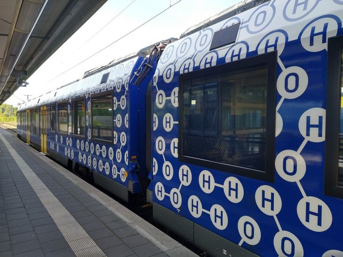
Image: Hydrogen fuel cell iLint by Jedesto, licensed under CC BY-SA 4.0.