
Indian Railways’ initiative to deploy its first indigenous hydrogen-powered train under the “Hydrogen for Heritage” program represents a high-profile demonstration of zero-emission heavy transit. While public attention focuses on the environmental milestone of replacing diesel locomotives on non-electrified routes, propulsion engineers must look at the rigorous thermodynamic and electrical trade-offs underlying this shift. Transitioning a multi-car trainset to a Proton Exchange Membrane Fuel Cell (PEMFC) hybrid system is far more complex than swapping an internal combustion engine for a fuel stack—it is an intricate balance-of-plant (BoP) exercise involving severe thermal dissipation constraints, high-voltage DC-DC conversion, dynamic degradation mitigation, and stringent upstream chemical engineering.
Powertrain Dynamics: Stack Polarisation and Battery Hybridisation
Heavy rail traction profiles demand extreme peak power during launch and steep gradient ascent, followed by extended cruising intervals at variable load. Operating a PEMFC directly across this dynamic torque-speed curve introduces severe durability penalties. PEM stacks exhibit maximum electrical efficiency (ηstack ≈ 55–60% lower heating value) at low to intermediate current densities (0.4–0.7 A/cm2, corresponding to cell voltages around 0.70–0.75 V). Pushing the stack into high current density regimes (1.5–2.0 A/cm2) to meet sudden acceleration spikes drops cell voltage down to ~0.55 V, driving dramatic ohmic losses and accelerating membrane dehydration stress, carbon support corrosion, and platinum catalyst dissolution.
To safeguard the fuel cell, the locomotive architecture relies on a Lithium-Ion Battery Energy Storage System (BESS)—typically utilizing Lithium Titanate Oxide (LTO) chemistry for high C-rate capability—for transient peak-shaving. The PEMFC acts as a steady-state base load provider, operating strictly within its high-efficiency zone, while a bi-directional multi-phase DC-DC converter modulates power flow from the battery during acceleration. Furthermore, regenerative braking redirects kinetic energy through the traction inverters back into the battery at charge rates up to 2C–3C. This hybrid configuration prevents rapid cell potential cycling (ΔV/Δt), extending PEM stack operating life from under 10,000 hours to an industry-viable 25,000–30,000 hours.
“Designing fuel cell propulsion for heavy rail is fundamentally a balance between heat rejection limits within tight loading gauges and high-purity water management from electrolyzer stack to fuel cell exhaust.”
Thermal Management and Parasitic BoP Loads
One of the most critical engineering bottlenecks in hydrail design is heat rejection. Internal combustion engines reject over 50% of their waste heat through high-temperature exhaust gas (500–600 °C), leaving a manageable delta-T for liquid cooling radiators. Conversely, a PEMFC operates at a low temperature window (65–85 °C). Because exhaust gas consists primarily of warm moist air and water vapor, over 95% of stack waste heat must be rejected via liquid coolant loops. With ambient design temperatures reaching 45 °C on many regional networks, the driving temperature differential (ΔT) for radiator heat transfer drops to a narrow 20–30 °C.
To dissipate a typical 1.2 MW waste heat load under these restricted ΔT conditions, cooling airflow must increase exponentially. High-flow coolant pumps and massive variable-speed radiator fans dramatically expand onboard parasitic power draw. Combined with the motorized scroll compressor supplying cathode air at 1.5–2.5 bar(g) and stoichiometry above 2.0, balance-of-plant components can consume 12% to 18% of total gross stack power output. Optimizing coolant loop piping, minimizing stack manifold pressure drops, and engineering variable-geometry compressor stages are vital to preventing net system efficiency from dropping below 40%.
Upstream Infrastructure: Electrolyzer Performance and Water Treatment Limits
A hydrogen locomotive is only as clean and reliable as its fueling ecosystem. Fuel cell stacks are exceptionally sensitive to chemical contaminants; ISO 14687 Grade D standards dictate maximum allowable limits of 0.2 ppm for carbon monoxide, 0.004 ppm for total sulfur compounds, and 5 ppm for water vapor. Injecting lower-grade hydrogen rapidly poisons platinum catalysts via irreversible chemisorption, leading to permanent mass-transport performance losses.
This places strict performance demands on the fueling depot’s upstream electrolyzer plant. Modern Proton Exchange Membrane (PEM) and Alkaline Electrolyzer (AEL) installations consume roughly 50 to 55 kWh of electrical energy per kilogram of produced H2 at 30 bar outlet pressure. However, the true baseline for electrolyzer longevity and gas purity lies in the water treatment infrastructure. Raw feed water must pass through multi-stage Reverse Osmosis (RO) followed by Continuous Electrodeionization (EDI) to reach ultra-pure water (UPW) standards:
- Electrical conductivity: < 0.1 µS/cm (resistivity > 10 MΩ·cm)
- Total Organic Carbon (TOC): < 50 ppb
- Silica content: < 10 ppb
For every 1 kg of H2 produced via electrolysis, theoretically 9 kg of stoichiometric H2O is consumed. However, actual water treatment plant requirements—accounting for RO recovery rates (typically 70–75%) and EDI blowdown—mandate a raw water intake of 12 to 15 kg per kilogram of hydrogen. Without precise real-time conductivity and total dissolved solids (TDS) monitoring, mineral scaling on electrolyzer porous transport layers causes localized current distribution hot spots, cell degradation, and premature stack breakdown.
Economic Realities and Strategic Deployment
Evaluating the economic viability of fuel cell rolling stock requires analyzing systemic round-trip efficiency (RTE) against direct overhead catenary electrification. Standard AC catenary electrification achieves a well-to-wheel efficiency of 75–85%. In contrast, the green hydrogen pathway—comprising renewable generation, electrolyzer stack conversion (η ≈ 65–70%), compression to 350/700 bar (consuming 3–5 kWh/kg), point-of-use distribution, and onboard PEMFC conversion (η ≈ 45–50%)—yields an overall well-to-wheel efficiency of 28–34%.
Despite this efficiency gap, hydrogen rolling stock becomes highly attractive when analyzing capital expenditure (CAPEX). Overhead catenary electrification requires linear CAPEX of approximately 2.5M per track kilometer, driven by substations, overhead wire networks, clearance civil works, and signaling isolation. For low-density, remote, or heritage feeder routes running fewer than 20 train trips daily, catenary installation is economically unviable. On these lines, localized hydrogen production via a centralized electrolyzer and water treatment facility, paired with hybrid onboard fuel cell storage, offers a faster deployment timeline and lower life-cycle operational costs.
Practical Takeaways for Systems Engineers
For engineering teams designing heavy-transport hydrogen systems and supply hubs, three core integration principles apply:
1. Decouple Dynamic Loads from the Fuel Cell: Size high-power LTO or NMC battery packs to absorb dynamic step-changes. Restrict fuel cell current ramp rates to under 5% per second to prevent catalyst degradation and localized reactant starvation.
2. Treat Water Quality as a Primary System Asset: Budget for redundant RO-EDI loops with automated shut-off systems at electrolyzer refueling hubs. Sub-microSiemens water feed is non-negotiable for stack lifetime economics.
3. Design BoP for Worst-Case Ambient Deltas: Size thermal management systems for maximum ambient envelope limits (ΔT ≤ 25 °C) and select high-efficiency DC-DC boost converters to keep parasitic auxiliary loads below 12% of total stack capacity.
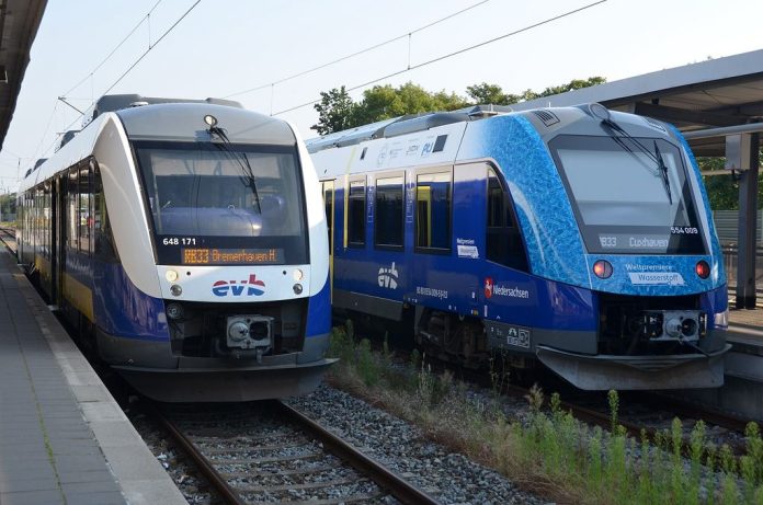
Image: Alstom Coradia Wasserstoff- und Dieseltriebwagen der EVB in Bremerhaven by Olga Ernst, licensed under CC BY-SA 4.0.