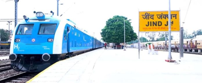

The announcement that Indian Railways is embarking on field trials for its first hydrogen-powered Diesel Electric Multiple Unit (DEMU) rake under the National Green Hydrogen Mission marks a significant public commitment to decarbonizing non-electrified rail corridors. Retrospectively fitting a traditional diesel-electric rolling stock chassis with a Proton Exchange Membrane Fuel Cell (PEMFC) powerpack, high-pressure 350-bar Type IV storage, and dynamic battery buffering is a complex engineering task. For system integrators and power engineers, this project highlights key challenges in heavy-duty fuel cell conversions: managing electrochemical transients, handling waste heat, and establishing the upstream green hydrogen electrolyzer and water treatment infrastructure needed to support daily operations.
Electrochemical Dynamics and the Thermal Dissipation Bottleneck
At the core of any fuel cell rail conversion is the mismatch between the load profile of heavy traction motors and the operating constraints of PEMFC stacks. During acceleration, a regional passenger train demands instantaneous power surges of 1.2 MW to 1.8 MW. Proton exchange membranes, however, exhibit slow dynamic response characteristics. Rapid load stepping forces local reactant starvation, accelerating platinum catalyst dissolution and membrane degradation. Slew rates must be constrained to safe operational envelopes, typically under 0.2 A/cm2 per second.
To shield the fuel cell stack from these high-amplitude dynamic cycles, a hybrid propulsion architecture is mandatory. High-power Lithium Iron Phosphate (LFP) or Lithium Titanate Oxide (LTO) battery banks must act as a buffer. The PEMFC stack is sized for steady-state cruise demand—operating at a optimized thermodynamic efficiency point of 52% to 55% (Lower Heating Value basis)—while the battery array delivers peak power during acceleration and absorbs regenerative braking energy. This hybridization reduces stack cycling, extending the operational life of the membrane electrode assembly (MEA) beyond 20,000 hours.
“The primary challenge in tropical fuel cell rail integrations is not power density, but thermal rejection: operating at 70°C in a 45°C ambient environment leaves a temperature differential of just 25°C.”
A more difficult engineering hurdle on onboard rail platforms is low-temperature heat rejection. While internal combustion engines reject waste heat at exhaust temperatures exceeding 500°C, a PEMFC operates between 65°C and 80°C. For every kilowatt of electricity generated, the stack rejects roughly 1.0 to 1.2 kW of thermal energy. In high ambient operational conditions—such as summer temperatures in regional India reaching 45°C—the log mean temperature difference (LMTD) between the liquid coolant loop and the ambient air shrinks to roughly 20°C to 25°C. Consequently, heat exchanger surface areas and radiator fan power consumption must scale by a factor of three relative to an equivalent diesel powertrain, presenting severe volumetric and weight constraint challenges on standard Broad Gauge roof profiles.
Upstream Infrastructure: Electrolyzer Integration and Dispensing
A fuel cell train is only as clean as its primary energy feedstock. To supply a single retrofitted DEMU rake consuming an estimated 300 kg to 350 kg of H2 per operational day, dedicated refueling infrastructure must be established at regional depots. This requires a precise balance-of-plant (BOP) design for on-site green hydrogen generation.
Electrolyzer Selection and Efficiency Metrics
For rail depot refueling hubs, selection typically falls between Alkaline Electrolysis (AEL) and Proton Exchange Membrane (PEM) electrolyzers:
- PEM Electrolyzers: Offer fast dynamic ramping (0% to 100% load in seconds), high current densities (>2.0 A/cm2), and elevated differential pressure output (30 to 50 bar), reducing downstream compression energy. However, they rely on precious metal catalysts (Iridium, Platinum) and carry higher capital costs.
- Alkaline Electrolyzers: Feature lower stack CapEx and proven durability using non-precious catalysts (Nickel-based), but operate at lower current densities (0.2 to 0.6 A/cm2), require corrosive KOH liquid electrolyte management, and respond slowly to dynamic renewable power inputs.
At the stack level, modern PEM units consume approximately 50 to 55 kWh/kg H2. When factoring in high-pressure compression (boosting output pressure from 30 bar to the 450–500 bar required for cascade filling of 350-bar onboard Type IV cylinders), chilling systems (-40°C pre-cooling to prevent composite vessel overheating during fast filling), and auxilliary BOP loads, the site-level specific energy consumption reaches 62 to 68 kWh/kg H2.
Water Treatment: The Critical Raw Material for Green Hydrogen
A frequently overlooked aspect of green hydrogen infrastructure is the strict requirement for feedstock water purity. Water fed into an electrolyzer stack must undergo extensive treatment to prevent irreversible stack contamination.
Stoichiometrically, splitting water requires 8.94 kg of pure H2O per 1 kg of produced H2. In practical industrial operations, system blowdown, backwashing, and purification losses elevate this requirement to 18 to 25 liters of raw water per kilogram of hydrogen produced. For an electrolyzer plant serving a small train fleet consuming 1,000 kg H2 daily, raw water intake exceeds 25,000 liters per day.
Feedstock Quality Requirements
PEM electrolyzer membranes demand ASTM Type I ultrapure water with an electrical conductivity under 0.056 µS/cm (resistivity > 18.2 MΩ·cm) and Total Organic Carbon (TOC) levels under 50 ppb. Trace multivalent cations (Fe2+, Ca2+, Mg2+) or chlorine ions poison the membrane’s sulfonic acid sites and corrode titanium bipolar plates, leading to rapid performance decay.
To achieve this purity from typical regional groundwater or surface sources, a robust multi-stage water treatment plant (WTP) is essential:
- Pre-Filtration: Multi-media filtration and activated carbon beds to reduce silt density index (SDI) and remove free chlorine.
- Primary Desalination: Double-pass Reverse Osmosis (RO) systems to remove >99% of dissolved inorganic ions and particulates.
- Polishing: Continuous Electrodeionization (EDI) coupled with a final mixed-bed ion-exchange resin to lower ionic conductivity to sub-microSiemens levels.
- Degasification: Membrane contactors to strip dissolved O2 and CO2 gases, preventing parasitic side reactions and oxidative stress within the electrolyzer stack.
Engineering Reality: Economics and System Efficiency
From an overall energy conversion perspective, hydrogen rail exhibits a low Well-to-Wheel (WTW) efficiency compared to direct catenary electrification:
Direct Catenary Electric Rail: Renewables → Transmission (92%) → Substation/Overhead Line (95%) → Traction Inverter/Motor (90%) = ~78% WTW Efficiency
Hydrogen Fuel Cell Rail: Renewables → Electrolyzer (65%) → Compression & Transport (90%) → Fuel Cell Stack (50%) → Traction Inverter/Motor (90%) = ~26% WTW Efficiency
Because direct overhead catenary electrification is roughly three times more energy-efficient, hydrogen propulsion is not a direct substitute for high-density, main-line electrified rail corridors. Instead, its ideal application lies on low-density branch lines, remote routes, and heritage corridors where the high capital expenditure of overhead catenary infrastructure (2.0 million per route-kilometer) cannot be economically justified. For engineering teams evaluating rolling-stock retrofits, hydrogen should be viewed as an alternative to diesel on non-electrified routes, provided that the levelized cost of hydrogen (LCOH) can be driven down to 4.00/kg through low-cost renewable power and optimized balance-of-plant water and compression loops.