
Indian Railways’ scheduled deployment of its first hydrogen-powered passenger train on the 89-kilometer Jind–Sonipat route in Haryana marks an important trial for non-electrified regional transport. Converting legacy Diesel Electric Multiple Units (DEMUs) into hydrogen-battery hybrid trainsets offers a pragmatic brownfield route to eliminate trackside diesel emissions without waiting for full catenary installation. However, looking at this deployment purely as a rolling-stock retrofit misses the broader engineering reality. Replacing a 1,000 kW diesel engine with Proton Exchange Membrane (PEM) fuel cells introduces complex thermodynamic balance-of-plant (BoP) challenges, delicate dynamic buffering requirements, and a high-purity water treatment chain that dictates whether the upstream green hydrogen generator operates reliably or suffers premature stack decay.
Thermodynamics and Onboard Powertrain Integration
Retrofitting hydrogen powertrains into existing rolling stock loading gauges forces severe spatial and thermal trade-offs. While an internal combustion engine rejects roughly half of its waste heat through high-temperature exhaust gas (450 °C to 550 °C), a PEM fuel cell stack operates at a modest internal temperature of 65 °C to 80 °C, dissipating nearly all waste heat through its liquid cooling loop. At an operational electrical efficiency of 50% to 55% (Lower Heating Value basis), a 1 MW fuel cell power plant generates roughly 900 kW of waste heat at full load.
In Northern India, where summer ambient air temperatures frequently top 45 °C, the log mean temperature difference (LMTD) between the fuel cell coolant and ambient air shrinks to under 30 °C. By contrast, a conventional diesel radiator operates with an LMTD exceeding 80 °C. To reject equal thermal energy, a PEM fuel cell system requires roughly three times the heat-exchanger surface area and volumetric airflow. On a retrofitted DEMU, expanding radiator footprints increases parasite blower fan loads, which can consume 10% to 14% of gross stack electrical output during peak summer conditions unless mitigated by intelligent thermal control strategies.
Hybridization and Dynamic Buffer Sizing
To shield the PEM stacks from rapid thermal cycling and localized reactant starvation, the propulsion architecture must decouple the fuel cell from transient acceleration spikes. Integrating a High-Power Lithium Titanate Oxide (LTO) or Lithium Iron Phosphate (LFP) battery pack enables steady-state stack operation. Operating the fuel cell at a continuous current density of 0.6 to 0.8 A/cm2 minimizes membrane voltage degradation and prevents platinum catalyst dissolution.
The battery buffer handles dynamic duty cycles, delivering up to 5C discharge rates during initial train launch and absorbing up to 85% of kinetic energy during regenerative braking. This dual-source configuration optimizes net hydrogen consumption per train-kilometer, but requires precision state-of-charge management to preserve battery health over thousands of shallow duty cycles.
“The true bottleneck of hydrogen rail is rarely the fuel cell on the roof; it is the quality of the water fed to the electrolyzer at the depot and the thermal radiator margins on the train.”
Upstream Infrastructure: Water Treatment and Electrolyzer Stoichiometry
While zero direct emissions occur at the train’s exhaust, the environmental and operational viability of the Jind–Sonipat line relies on the green hydrogen supply chain at the refueling terminal. Producing hydrogen fuel cell vehicle (FCV) grade gas—conforming strictly to ISO 14687 Grade D standards—demands rigorous upstream water treatment. PEM fuel cells are hyper-sensitive to trace contaminants: carbon monoxide levels above 0.2 ppm, hydrogen sulfide above 0.004 ppm, or ammonia above 0.1 ppm permanently poison the membrane electrode assembly (MEA).
Generating high-purity hydrogen via water electrolysis requires exceptionally clean feed water. Water splitting has a theoretical stoichiometry of 8.93 liters of pure H2O per kilogram of H2. In practice, system purge losses, cooling requirements, and water treatment reject streams raise raw water demand significantly:
1. Pre-filtration and Dechlorination: Raw groundwater or municipal supply undergoes multi-media filtration and activated carbon adsorption to eliminate suspended solids and free chlorine, which would ruin downstream reverse osmosis membranes.
2. Double-Pass Reverse Osmosis (RO): Removes over 99% of dissolved ions, reducing Total Dissolved Solids (TDS) from typical raw levels (>500 mg/L) to under 10 mg/L.
3. Continuous Electro-Deionization (EDI) & Mixed-Bed Polishing: Polishes water quality to an electrical resistivity of 18.2 MΩ·cm at 25 °C, with Total Organic Carbon (TOC) kept below 5 ppb. Trace metallic cations (Fe2+, Cu2+, Ca2+) must be eliminated, as even sub-ppm levels accelerate Fenton-type degradation reactions within the electrolyzer membrane.
Accounting for RO brine rejection, an industrial green hydrogen production facility consumes between 20 and 25 liters of raw water intake per kilogram of purified H2 produced. For a 1 MW electrolyzer generating ~200 kg of H2 per day at standard efficiency (52 kWh/kg H2 system rating), the water treatment system must reliably deliver over 5,000 liters of ultrapure water daily without interruption.
Economic Economics: LCOH vs. Catenary Electrification
Rail operators evaluating hydrogen against conventional 25 kV AC overhead catenary electrification face clear capital-versus-operational cost tradeoffs. Catenary infrastructure demands high upfront capital expenditure (typically 2.0 million per track-kilometer), making it economically suited for high-density mainlines. Hydrogen rolling stock shifts capital expenditure from linear track infrastructure to localized refueling hubs and specialized trainsets, making it attractive for low-density branch lines like Jind–Sonipat.
However, operational costs remain constrained by the Levelized Cost of Hydrogen (LCOH). Assuming a green electricity tariff of 3.45 per kg of H2. Factoring in capital recovery for PEM electrolyzers, high-pressure compression (boosting from 30 bar stack pressure to 500 bar storage), demineralized water treatment OPEX ($0.10/kg H2), and dispenser maintenance, delivered LCOH at the nozzle currently ranges between 7.50 per kg.
At an average operational traction consumption of 0.40 kg H2 per train-kilometer for a regional DEMU rake, operational cost parity with conventional diesel requires a delivered LCOH below $3.80 per kg. Achieving this price target requires lower power costs, longer electrolyzer stack lifespans beyond 80,000 operating hours, and localized, high-efficiency water treatment systems.
Engineering Guidelines for System Integration
To ensure long-term viability as hydrogen rail projects scale from initial pilots to commercial fleets, field engineers and system integrators should focus on key design parameters:
- Radiator Subsystem Sizing: Size coolant heat exchangers with a 15% to 20% surface area safety margin above standard nominal conditions to account for dust fouling and peak summer ambient extremes in arid rail corridors.
- Stack-to-Battery Ratio: Target a dynamic power split where the fuel cell handles baseline cruising power (~40–50% of peak installed power), allowing high-C-rate batteries to cover transient acceleration load steps.
- Feed Water Monitoring: Install inline conductivity sensors and TOC analyzers upstream of the electrolyzer cell stacks with automated shut-off trip points set at <17.5 MΩ·cm to prevent water-borne catalyst poisoning.
- Cascaded Storage Compression: Utilize a three-tier cascaded high-pressure storage array (200 bar, 350 bar, 500 bar) at refueling stations to reduce compressor energy consumption by up to 25% during rapid fill cycles.
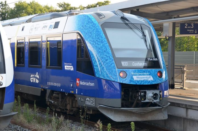
Image: Alstom Coradia iLint 554 009 Wasserstoffzug der EVB by Olga Ernst, licensed under CC BY-SA 4.0.