
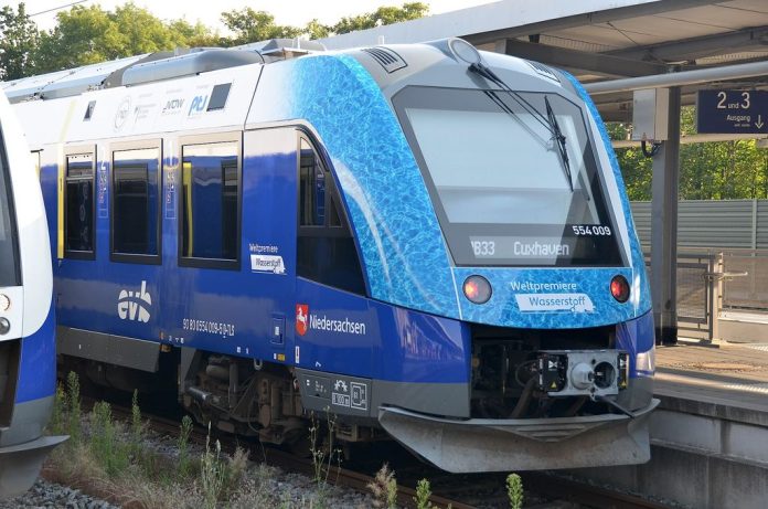

The recent announcement that Indian Railways is deploying 35 hydrogen-fueled trains under its “Hydrogen for Heritage” program highlights a growing global interest in fuel cell hybrid rail vehicles. These trainsets, designed around Proton Exchange Membrane Fuel Cells (PEMFC), Lithium-ion buffer batteries, and 350-bar onboard storage, target non-electrified, ecologically sensitive routes. While substituting Diesel Multiple Units (DMUs) with localized zero-emission powertrains is politically compelling, engineering a reliable, scalable, and economically viable hydrogen rail network requires looking past the vehicle chassis and addressing the complex thermodynamics, balance-of-plant (BoP) requirements, and fuel production supply chain.
1. Powertrain Dynamics and Thermal Management Bottlenecks
At the vehicle level, integrating a fuel cell into a heavy rail application requires balancing dynamic load response with component longevity. PEMFC stacks excel at steady-state power output but suffer accelerated degradation under rapid thermal and electrical cycling. During high-torque acceleration phases, transient power demand must be buffered by a high-rate Lithium-ion battery system—typically Lithium Titanate (LTO) or Nickel Manganese Cobalt (NMC) chemistries capable of 3C to 5C continuous discharge rates. An advanced Energy Management System (EMS) maintains the PEMFC within a narrow, optimized operating window (typically between 0.6 A/cm2 and 1.2 A/cm2 current density) while the battery absorbs peak traction loads and recovers kinetic energy during regenerative braking.
However, the most significant vehicle-level engineering hurdle is thermal rejection. Internal combustion engines operate at coolant temperatures of 90°C to 105°C, yielding a substantial temperature differential (ΔT) relative to ambient air. A PEMFC stack operates at a much lower window of 60°C to 75°C. In high-ambient environments—where ambient temperatures can reach 40°C to 45°C—the effective ΔT drops to just 15°C to 30°C.
“Because a fuel cell stack rejects almost all non-electric energy directly to its liquid coolant loop rather than through exhaust gas, heat exchanger surface areas must increase by 200% to 300% compared to equivalent diesel engines, driving up parasitic cooling fan loads to as much as 12% of gross stack output.”
2. Refueling Infrastructure and Compression Mechanics
Onboard storage for rail applications relies primarily on Type IV carbon-fiber composite cylinders pressurized to 350 bar. While 700 bar is common in light-duty passenger vehicles, 350 bar remains the sweet spot for rail due to lower volumetric constraints, lower compression energy requirements, and superior mechanical durability under high-vibration duty cycles.
The primary infrastructure challenge lies in high-flow dispensing and compression Balance of Plant (BoP):
- Compression Work: Boosting hydrogen from a low-pressure production buffer (typically 30 bar from an electrolyzer) to a 450-bar cascade storage system requires multi-stage ionic or diaphragm compressors, consuming roughly 3.0 to 4.5 kWh/kg of H2.
- Thermal Pre-cooling: Rapidly filling multi-kilogram train storage arrays generates significant heat of compression. To prevent the composite cylinder polymer liner from exceeding its maximum temperature limit of 85°C, refueling hubs must incorporate refrigeration units to pre-cool the hydrogen stream to -20°C or -40°C prior to dispensing.
- Buffering & Delivery: A single 4-car trainset can require 250 kg to 400 kg of hydrogen per day. Continuous fueling of a 35-train fleet demands high-flow dispensing systems capable of delivering up to 7.2 kg/min, far exceeding standard automotive protocols.
3. Upstream Water Treatment and Electrolyzer Coupling
A hydrogen train is only as clean as the upstream generation process. Green hydrogen production requires coupling renewable power to industrial electrolyzer plants—either Proton Exchange Membrane (PEM) or Alkaline Electrolysis (AEL) units. To prevent rapid membrane poisoning and electrode degradation, electrolyzers demand extremely high-purity feed water.
Standard municipal water or raw ground water contains dissolved solids, silica, and organic contaminants that must be removed through multi-stage industrial water treatment plants before reaching the stack:
- Pre-treatment: Multi-media filtration and activated carbon beds remove suspended solids and free chlorine.
- Primary Desalination: Double-pass Reverse Osmosis (RO) systems reject over 99% of dissolved ions, reducing total dissolved solids (TDS) to low single-digit ppm levels.
- Polishing: Continuous Electrodeionization (CEDI) or mixed-bed ion exchange resins polish the water to achieve an electrical conductivity below 0.1 µS/cm (resistivity > 10 MΩ·cm) and total organic carbon (TOC) below 50 ppb.
Stoichiometrically, splitting water yields 1 kg of H2 for every 9 kg of pure H2O. However, real-world balance-of-plant inefficiencies, reverse osmosis reject streams, cooling tower evaporation, and system blowdown mean that a commercial electrolyzer facility actually consumes between 18 kg and 25 kg of raw water per kilogram of produced green hydrogen. In arid or water-stressed operational corridors, designing closed-loop water recovery systems and high-recovery RO configurations is mandatory.
Furthermore, the output hydrogen must be purified to meet ISO 14687 Grade D standards (< 0.005 ppm CO, < 0.04 ppm total sulfur) before entering the train's fuel cell. Trace impurities from inadequate electrolyzer drying or compressor oil carryover will permanently poison the noble metal catalysts in the vehicle stack.
4. Efficiency Trade-Offs and Economic Realities
From an operational perspective, engineers must evaluate the overall Well-to-Wheel (WTW) energy efficiency of hydrogen fuel cell rail against direct electrification via overhead catenary systems (OCS):
Well-to-Wheel Efficiency Breakdown:
- Electrolyzer conversion: ~55 kWh/kg H2 (~60% LHV efficiency)
- Compression, pre-cooling, and transport: ~5 kWh/kg H2
- PEMFC stack reconversion to electricity: ~50% efficiency
- Drive motor & inverter efficiency: ~90%
- Net System WTW Efficiency: ~22% to 26%
By contrast, direct catenary electrification achieves a net grid-to-wheel efficiency of 75% to 85%. Therefore, wherever traffic density justifies the capital expenditure of overhead lines (2.5M per track kilometer), direct electrification is thermodynamically and economically superior.
Hydrogen fuel cell trains find their true engineering niche on low-density branch lines, remote scenic corridors, or geographically constrained routes where the high capital cost of sub-stations, catenary structures, and tunneling clearances renders OCS impractical. For these routes, fuel cell hybrids offer a flexible, localized solution—provided the balance of plant, water purification infrastructure, and thermal management systems are rigorously engineered from the ground up.
Image: Alstom Coradia iLint 554 009 Wasserstoffzug der EVB by Olga Ernst, licensed under CC BY-SA 4.0.