
The announced initiative by Indian Railways to convert legacy Diesel Electric Multiple Units (DEMUs) into hydrogen fuel cell hybrids under the “Hydrogen for Heritage” project highlights a growing global trend: using localized, zero-emission powertrains for non-electrified regional and ecologically sensitive rail lines. While retrofitting historic narrow-gauge and meter-gauge stock offers an attractive pathway to decarbonization, executing this transition reliably demands rigorous attention to the underlying system engineering. Converting a diesel engine into a hydrogen-electric system requires far more than dropping a fuel cell under the hood—it necessitates a complete redesign of onboard power electronics, thermal management, compressed gas storage, and the upstream fueling infrastructure.
Electrochemical Powertrain Architecture and Dynamic Buffering
At the core of a hydrogen-powered train (hydrail) is the Proton Exchange Membrane (PEM) fuel cell stack. PEM technology is universally selected for heavy transport due to its high power density (typically 3.0 to 4.5 kW/L stack level), low operating temperature (60 °C to 80 °C), and rapid cold-start capabilities. However, a PEM fuel cell operating as a standalone prime mover faces severe durability constraints when subjected to the dynamic load profiles typical of rail operations.
During vehicle launch and heavy gradient ascents, power demand spikes rapidly. Subjecting a PEM stack to raw transient cycling accelerates catalyst degradation. Rapid swings in cell potential (between open-circuit voltage at ~0.95 V and full load at ~0.60 V) induce platinum particle dissolution, carbon support corrosion, and mechanical stress across the perfluorosulfonic acid (PFSA) membrane. Furthermore, operating at low cell voltages under high current densities (exceeding 1.5 A/cm2) drops stack voltage efficiency from a peak of ~60% Lower Heating Value (LHV) down to under 45%, converting excess input energy directly into waste heat.
To preserve stack lifetime and maximize system efficiency, a modern hydrail platform uses a fuel-cell-dominant hybrid architecture. In this topology, a high-power Lithium-Ion Energy Storage System—often utilizing Lithium Titanate Oxide (LTO) or Lithium Iron Phosphate (LFP) chemistries—acts as a dynamic power buffer. The fuel cell operates in a load-following mode with bounded ramp rates (typically limited to <10% rated power per second), supplying the baseline average power demand. The battery pack absorbs dynamic load spikes, delivering discharge rates of 3C to 5C during acceleration and capturing regenerative braking energy during deceleration.
“Designing hydrail systems is fundamentally an integrated balance-of-plant problem: the real engineering complexity shifts from the fuel cell stack itself to managing thermal dissipation onboard and upstream water purity at the electrolyzer terminal.”
Managing energy flow between the fuel cell stack, battery bank, and traction motors requires multi-phase, interleaved bidirectional DC-DC converters. These converters step up the variable stack output voltage (which drops as current increases along its polarization curve) to a stable, high-voltage DC bus (typically 600 V to 750 V DC), supplying the traction inverters that drive the AC induction or permanent magnet synchronous motors.
Onboard Fuel Storage, Volumetric Constraints, and Compression
Packaging hydrogen storage within narrow-gauge and meter-gauge rail envelopes presents steep spatial challenges. Diesel fuel possesses a volumetric energy density of roughly 36 MJ/L. By comparison, gaseous hydrogen at 350 bar (35 MPa) yields roughly 2.7 MJ/L—less than 8% of diesel’s energy per unit volume.
For regional rail applications operating on 350 bar compressed gas systems, storage standardizes on Type IV composite pressure vessels (high-density polyethylene liners wrapped in carbon fiber with epoxy resin). Achieving the required daily range for a regional train (consuming roughly 250 kg to 350 kg of H2 per daily operational run) requires mounting large bank arrays, often on the roof structure or in dedicated power cars.
Roof-mounting demands careful structural stress analysis to manage dynamic axle load distribution and center-of-gravity shifts. Moreover, fast refueling of 350 bar cylinders requires managing the thermodynamic heating of the gas inside the cylinder. As gas compresses into the tank, temperature rises according to Joule-Thomson behavior at high pressures. Storage cylinder skin temperatures must remain strictly below 85 °C to prevent composite liner degradation, requiring hydrogen refuelers to incorporate pre-cooling refrigeration units capable of chilling fuel down to -20 °C to -40 °C prior to dispensing.
Upstream Balance-of-Plant: Electrolyzer and Water Treatment Integration
The green credentials of any hydrogen train depend entirely on the upstream production ecosystem. Generating 300 kg of green hydrogen per day to power a train set requires a dedicated electrolyzer system rated at approximately 750 kW to 1.0 MW, assuming a specific stack energy consumption of 50 to 55 kWh/kg H2.
Whether utilizing Proton Exchange Membrane (PEM) or Alkaline Electrolysis (AEL) units, the performance and stack longevity of the electrolyzer depend heavily on the upstream water treatment infrastructure. Stoichiometrically, splitting water requires 8.94 liters of pure H2O per kilogram of H2 produced. However, process inefficiencies, continuous blowdown, and purification losses elevate actual raw water consumption to 12–15 liters per kilogram of H2.
Electrolyzer Water Quality Requirements
PEM electrolyzers require Ultrapure Water (UPW) compliant with ASTM Type I or ISO 3696 Grade 1 specifications, requiring electrical conductivity below 0.1 µS/cm (resistivity > 10 MΩ·cm) and Total Organic Carbon (TOC) under 50 ppb. Trace contaminants in feedwater present catastrophic failure modes for electrolyzer stacks:
- Transition Metal Ions (Fe, Cu, Ni): Poison the catalyst layers and accelerate membrane degradation via Fenton-type reactions that generate destructive hydroxyl radicals.
- Divalent Cations (Ca2+, Mg2+): Precipitate on cathode surfaces, blocking active catalyst sites and causing rapid cell overpotential spikes.
- Halides (Cl–, F–): Cause severe localized corrosion on titanium-coated current collectors and bipolar plates.
To achieve this purity, the industrial water treatment train upstream of the electrolyzer must integrate multiple unit operations: multi-media sand filtration, water softening, dual-pass Reverse Osmosis (RO), Continuous Electrodeionization (EDI), and terminal mixed-bed ion-exchange resin polishing. Designing robust water treatment systems that run reliably under variable municipal or ground feedwater quality is essential for preserving multi-million-dollar electrolyzer stack investments.
Economic Mechanics and Operational Reality for Rail Systems
From an efficiency perspective, green hydrogen rail operates at a well-to-wheel efficiency of approximately 28% to 34%, considering electrolysis losses (~65% LHV efficiency), compression and transport (~90%), fuel cell conversion (~50–55%), and electric drive loss (~85%). Direct catenary electrification, by contrast, achieves well-to-wheel efficiencies exceeding 75%.
Consequently, hydrail is not a replacement for high-density mainlines where overhead catenary infrastructure is economically viable. Instead, it serves as an optimal solution for non-electrified branch lines, low-frequency rural routes, and heritage corridors where the capital cost of catenary installation (2.5M per track-kilometer) cannot be justified. For practitioners engineering these transitions, long-term success relies on evaluating the total cost of ownership (TCO)—balancing fuel cell stack replacement intervals (typically 20,000 to 30,000 operating hours), localized levelized cost of hydrogen (LCOH), and the operational reliability of upstream electrolyzer water treatment facilities.
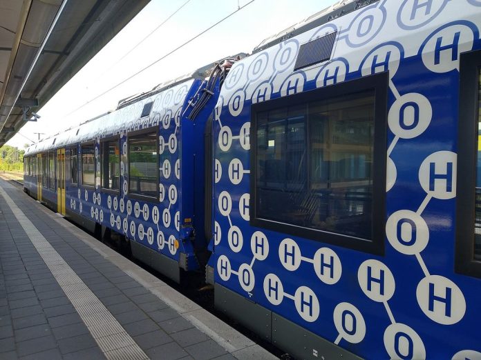
Image: Hydrogen fuel cell iLint by Jedesto, licensed under CC BY-SA 4.0.