

Key points
- ISO 15848-1 is a type-qualification standard, while ISO 15848-2 governs production batch testing.
- The standard classifies stem leakage by tightness (AH to CH for helium), mechanical endurance, and temperature range.
- Helium leakage is measured per unit of stem circumference in mg·s-1·m-1.
- Valves must endure repeated thermal cycles and up to 2,500 mechanical strokes without gland packing adjustments.
Valves account for more than half of all fugitive emissions in chemical plants and refineries. Fugitive emissions are uncaptured leaks that escape into the atmosphere from pressurised process equipment. Most of these leaks escape from two places: the moving valve stem and the static body flange.
Environmental regulations and safety rules require industrial plants to stop these leaks. Process operators handle volatile organic compounds, toxic chemicals, and flammable gases like hydrogen. A leaking valve wastes product, creates an explosion hazard, and pollutes the air. To buy the right valve, you must know how well the stem packing holds pressure over thousands of strokes.
This is where testing under ISO 15848-1 comes into play. The standard creates a strict, repeatable laboratory test for valve manufacturers and buyers. It verifies that a specific valve design will not leak beyond defined limits over its design life.
Key terms in plain English
- Fugitive emission: Gas or vapour that leaks unintentionally from a pressurised component into the open air.
- Type test: A rigorous laboratory test on a sample valve to qualify an entire product line or design family.
- Stem seal: The soft packing rings or dynamic seals that prevent process fluid from leaking along the moving stem.
- Body seal: The static gasket or O-ring that seals the joint between valve body parts.
- Sniffing method: A leak detection method where an instrument probe draws air near the seal to measure local gas concentration in parts per million.
- Vacuum method: A leak detection method where a sealed metal hood captures all escaping helium to measure total leakage rate accurately.
Understanding the ISO 15848-1 standard
The standard carries the full title: Industrial valves — Measurement, test and qualification procedures for fugitive emissions — Part 1: Classification system and qualification procedures for type testing of valves. The International Organization for Standardization published the first edition in 2006 and updated it in 2015.
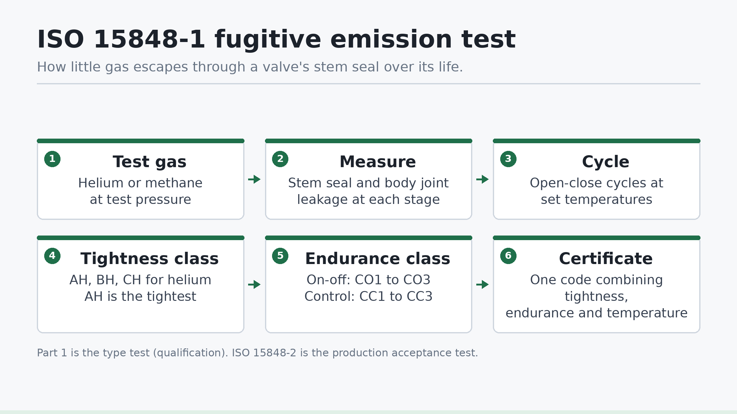
ISO 15848-1 serves as a prototype qualification test. You do not run this test on every production valve. Instead, the manufacturer tests one or two representative valves from a product family. Passing this test qualifies valves of similar size, pressure rating, and packing geometry.
By contrast, ISO 15848-2 defines production testing. Production testing is a short quality control check carried out on assembled valves before shipping. It uses sniffing or pressure drop methods at room temperature to catch manufacturing defects.
ISO 15848-1 uses either helium or methane as the test gas. Helium is an inert tracer gas with small molecules that pass through tiny leak paths. Methane represents real-world light hydrocarbon service. Most global buyers prefer helium because it allows precise mass spectrometer leak detection down to microscopic levels.
During the test, technicians measure leakage at both the valve stem seal and the body gasket joint. The stem seal moves continuously, making it the hardest part to seal. The body joint remains static, so its leakage threshold is much tighter.
Tightness classes in ISO 15848-1
The standard rates stem seal tightness into distinct letter classes based on the measured leakage rate. The measurement is normalised to the stem circumference. This ensures fair comparison between small valves and large valves.
For helium tracer gas, the standard defines three tightness classes:
- Class AH: Leakage less than or equal to 10-5 mg·s-1·m-1. This is the tightest class, often requiring bellows seals or advanced live-loaded polymer packing.
- Class BH: Leakage less than or equal to 10-4 mg·s-1·m-1. This is the common benchmark for high-performance chemical service with graphite or PTFE packing.
- Class CH: Leakage less than or equal to 10-2 mg·s-1·m-1. This level suits standard industrial service with conventional die-formed graphite rings.
For methane tracer gas, the standard evaluates leakage by sniffing in parts per million by volume (ppmv):
- Class AM: Leakage less than or equal to 50 ppmv.
- Class BM: Leakage less than or equal to 100 ppmv.
- Class CM: Leakage less than or equal to 500 ppmv.
Static body seals must meet a separate limit. Under helium testing, body joints must not exceed 10-6 mg·s-1·m-1 using the vacuum method. If measured by sniffing, body joints must show less than 50 ppmv for both helium and methane.
Endurance classes and mechanical cycles
Valves perform different duties in a plant. An on-off isolation valve might cycle once a week. A control valve can cycle every few seconds to adjust line pressure. ISO 15848-1 accounts for this difference by splitting valves into two endurance categories.
For isolating and on-off valves, the standard defines mechanical endurance classes designated by the letters CO:
- Class CO1: 200 mechanical cycles with 2 thermal cycles. This suits emergency isolation and infrequent shut-off duties.
- Class CO2: 1,500 mechanical cycles with 3 thermal cycles. This covers standard process isolation valves.
- Class CO3: 2,500 mechanical cycles with 4 thermal cycles. This proves long-term durability for high-cycle on-off service.
For control valves, the movements are smaller but far more frequent. The standard evaluates them over tens of thousands of short strokes, designated by the letters CC:
- Class CC1: 20,000 cycles with 2 thermal cycles.
- Class CC2: 60,000 cycles with 3 thermal cycles.
- Class CC3: 100,000 cycles with 4 thermal cycles.
In all classes, the manufacturer must not tighten the packing gland bolts during testing. If a technician adjusts the gland packing nuts to stop a leak, the standard records that adjustment. Only a limited number of packing adjustments are allowed, and each must be logged on the certificate.
Temperature classes and thermal cycling
Heat expands metal components and degrades packing rings. Cryogenic cold causes materials to shrink and embrittle. A seal that holds gas at 20 °C might fail completely at 300 °C.
ISO 15848-1 tests this behaviour by combining mechanical stroking with thermal cycling. The test protocol applies mechanical cycles at ambient room temperature, then heats or cools the valve to its rated test temperature while under internal gas pressure. The valve must stroke at the target temperature, cool back to ambient, and stroke again.
The standard specifies standard test temperature ratings:
- (t-196 °C): Liquid nitrogen cryogenic service.
- (t-46 °C): Low-temperature carbon steel service.
- (tRT): Room temperature service (-29 °C to +40 °C).
- (t200 °C): Medium heat service, common for PTFE blends.
- (t400 °C): High-temperature steam and hydrocarbon service, requiring expanded graphite.
How to read the ISO 15848-1 certificate code
When a valve passes qualification, ISO 15848-1 expresses its performance as a single alphanumeric string. This code tells you every critical boundary of the test.
Consider this real-world qualification marking:
ISO-FE AH - CO3 - SSA 0 - t(RT, 400 °C) - CL 300 - ISO 15848-1
Here is how to unpack each segment:
- ISO-FE: Identifies the test as an ISO Fugitive Emission qualification.
- AH: Tightness class AH (helium leak rate below 10-5 mg·s-1·m-1).
- CO3: Mechanical endurance class (2,500 mechanical cycles for on-off service).
- SSA 0: Stem seal adjustments made during the test. Zero means no packing adjustments were performed.
- t(RT, 400 °C): Tested from room temperature up to 400 °C with thermal cycles.
- CL 300: ASME pressure class rating of the test valve.
- ISO 15848-1: The governing standard reference.
A buyer can read this single line and know that the valve design handles high heat, cycles thousands of times, and releases negligible fugitive leaks.
Step-by-step test procedure
Running an ISO 15848-1 test requires strict test discipline and clean instrumentation. The test follows these distinct steps:
First, technicians clean and assemble the test valve. They inspect the stem surface finish, packing ring density, and gland torque. They mount a containment hood around the stem packing gland and another around the body flange joint.
Second, they pull a vacuum inside the containment hoods. They connect the hood output line directly to a calibrated helium mass spectrometer leak detector. This detector measures the background concentration of helium in the room to establish a clear baseline.
Third, technicians pressurise the valve cavity with 97 percent or purer helium gas. They set the pressure to the maximum rated working pressure per ASME B16.34 for that material and temperature. They measure initial static leakage at ambient temperature.
Fourth, the test actuator strokes the valve through its mechanical cycles. For Class CO1, the actuator performs open-close strokes at ambient temperature while instruments log leak rates continuously.
Fifth, the test bench heats the valve body to the target temperature using heating jackets. The internal helium pressure is adjusted to match the lower allowable pressure at high temperature per ASME B16.34. The valve strokes repeatedly at maximum heat.
Sixth, the assembly cools back to room temperature under pressure. Technicians measure the cold leak rate. Thermal cycling creates micro-gaps around the stem due to differential thermal expansion between steel and graphite. This step tests if the packing recovers its seal.
Finally, the actuator completes the final mechanical cycles. The technicians perform a final leakage measurement at ambient temperature and record whether any gland tightening occurred.
Worked example: calculating specific leakage rate
ISO 15848-1 does not compare raw detector flow rates directly. It normalises leakage to the stem circumference. Let us calculate whether a 50 mm (2-inch) Class 300 globe valve passes Class AH.
The valve has a polished stem with an outside diameter ($d$) of 25.0 mm. During the 400 °C cycle, the mass spectrometer measures a total helium leak rate of 3.5 × 10⁻⁷ milligrams per second (mg·s-1).
Step 1: Calculate the stem circumference in metres.
Stem diameter d = 25.0 mm = 0.025 m.
Circumference C = π × d = 3.1416 × 0.025 m = 0.07854 m.
Step 2: Calculate the specific leakage rate (Qs) per unit of stem circumference.
Qs = (Measured Leak Rate)/Circumference = (3.5 × 10⁻⁷ mg·s-1)/(0.07854 m)
Qs = 4.46 × 10⁻⁶ mg·s-1·m-1.
Step 3: Compare with ISO 15848-1 tightness thresholds.
The upper limit for Class AH is 1.0 × 10⁻⁵ mg·s-1·m-1.
Our calculated rate of 4.46 × 10⁻⁶ mg·s-1·m-1 is less than 1.0 × 10⁻⁵ mg·s-1·m-1.
The valve stem seal easily satisfies ISO 15848-1 Class AH.
Benchmarks: how the options compare
Engineers often confuse ISO 15848-1 with other fugitive emission standards like API 624 or API 641. The American Petroleum Institute (API) designs its standards around pass-fail criteria for specific valve designs. ISO 15848-1 provides a graded classification across all valve categories.
| Standard | Valve Types Covered | Tracer Gas | Leak Measurement Method | Pass Threshold | Mechanical Cycles | Source |
|---|---|---|---|---|---|---|
| ISO 15848-1 Class AH | All control and isolation valves | Helium | Vacuum hood method | ≤ 10-5 mg·s-1·m-1 | 200 to 100,000 cycles | ISO 15848-1:2015 |
| ISO 15848-1 Class BH | All control and isolation valves | Helium | Vacuum hood method | ≤ 10-4 mg·s-1·m-1 | 200 to 100,000 cycles | ISO 15848-1:2015 |
| ISO 15848-1 Class BM | All control and isolation valves | Methane | Sniffing (EPA Method 21) | ≤ 100 ppmv | 200 to 100,000 cycles | ISO 15848-1:2015 |
| API 624 | Rising stem steel valves with graphite | Methane | Sniffing (EPA Method 21) | ≤ 100 ppmv (no adjustments) | 310 cycles + 3 thermal cycles | API 624 2nd Edition |
| API 641 | Quarter-turn valves (ball, plug, butterfly) | Methane | Sniffing (EPA Method 21) | ≤ 100 ppmv (no adjustments) | 610 cycles + 3 thermal cycles | API 641 1st Edition |
| ISO 15848-2 | Production batch testing | Helium | Sniffing or pressure hold | Agreed between buyer and vendor | 0 to 5 cycles (room temp) | ISO 15848-2:2015 |
Packing design and qualification extension
You do not need to test every valve size in an engineering laboratory. ISO 15848-1 allows a successful test to qualify a family of valves, provided key design parameters match.
The standard establishes strict qualification extension limits:
- Stem diameter: A tested valve qualifies valves with stem diameters from half to double the tested diameter ($0.5d$ to $2d$).
- Pressure class: A test qualifies valves of the same class and one class rating higher (for example, testing Class 300 qualifies Class 300 and Class 600).
- Temperature rating: Qualification extends to any temperature between room temperature and the maximum tested temperature.
- Packing material: The packing rings in the production valve must use identical material, density, shape, and cross-section as the tested sample.
Valve designers use live-loaded gland systems to maintain seal load over time. Live-loading places Belleville disc springs beneath the gland nuts. As graphite packing consolidates or wears during mechanical strokes, the springs expand slightly. This keeps constant axial compression on the packing set without requiring manual bolt adjustment.
Checklist for engineers
- Confirm your required test gas: specify helium if you need vacuum mass spectrometry or methane if you track EPA Method 21 compliance.
- Determine valve duty: specify endurance Class CO for isolation service or Class CC for throttling control service.
- Match the test temperature class to your real process extremes, including steam clean-out or cryogenic cold.
- Check that the valve certificate reads “SSA 0” so you know no manual packing adjustments occurred during type testing.
- Verify that your stem diameter falls within the $0.5d$ to $2d$ qualification range of the manufacturer’s test certificate.
- Ensure static body gaskets meet the 50 ppmv sniffing or 10-6 mg·s-1·m-1 helium limit.
- Specify production testing under ISO 15848-2 as a purchase order check to ensure shop floor assembly quality.
What is happening now
Recent trade reports highlight ongoing research into gasket leakage across alternative test gases. Trade press coverage on valve-world.net in October 2026 examined leakage comparisons across different test mediums during EN 13555 testing. Matching laboratory gas leak rates to actual plant fluid behaviour remains an active focus for standards committees.
Frequently asked questions
What is the difference between ISO 15848-1 and ISO 15848-2?
ISO 15848-1 is a prototype qualification test that subjects a sample valve to mechanical cycling and thermal changes over several days. ISO 15848-2 is an inspection test performed on production valves at ambient room temperature before they leave the factory. Part 1 proves the valve design works, while Part 2 confirms the shop assembled the production batch properly.
Can an API 624 certified valve pass ISO 15848-1?
Many valves qualified to API 624 can meet ISO 15848-1 Class BH or BM. However, passing API 624 does not grant automatic ISO 15848-1 certification. API 624 uses methane sniffing across 310 cycles at up to 260 °C. ISO 15848-1 Class CO2 or CO3 tests valves over 1,500 to 2,500 cycles and often uses helium vacuum collection, which is far more sensitive.
Why does ISO 15848-1 normalise leakage to stem diameter?
A 100 mm valve stem has four times the circumference of a 25 mm stem. A larger stem circumference presents four times more contact area for potential leakage. Normalising the measured mass leak rate by stem circumference allows fair comparison between valves of different sizes.
Are packing adjustments allowed during an ISO 15848-1 test?
The standard discourages packing adjustments during qualification. However, it permits up to one adjustment for Class CO1 and up to three for Class CO3 if leakage spikes. Any adjustment must be declared on the certificate code under the SSA parameter. Global end-users generally demand an SSA 0 rating, proving zero manual adjustments.
If you are specifying valves for severe chemical duty, hydrogen service, or plant emission reduction programs, contact Avoltium for engineering support with fugitive emission testing protocols and valve selection.