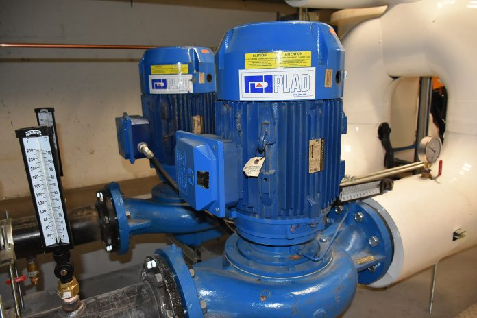

Cavitation is among the most destructive phenomena encountered in fluid handling systems. It erodes impellers, destroys mechanical seals, shears shafts, and produces distinct acoustic noise often described as pumping gravel. Preventing this mechanical deterioration begins during the front-end engineering design phase with a rigorous npsh calculation. If the pressure of the fluid entering the pump drops to or falls below its saturation vapour pressure, micro-bubbles of vapour flash into existence. As these vapour pockets sweep into regions of higher pressure along the impeller vane profiles, they collapse violently within microseconds, generating localized micro-jets with shockwave pressures exceeding 1,000 MPa (10,000 bar). Avoiding this damage requires an exact balance between the hydraulic physics of your suction piping and the internal design of the pump.
The Physics of Cavitation: NPSHa vs NPSHr
Net Positive Suction Head (NPSH) quantifies the net energy per unit weight present at the pump suction nozzle, measured above the liquid vapour pressure head. Engineers must balance two fundamentally distinct metrics: available head and required head.
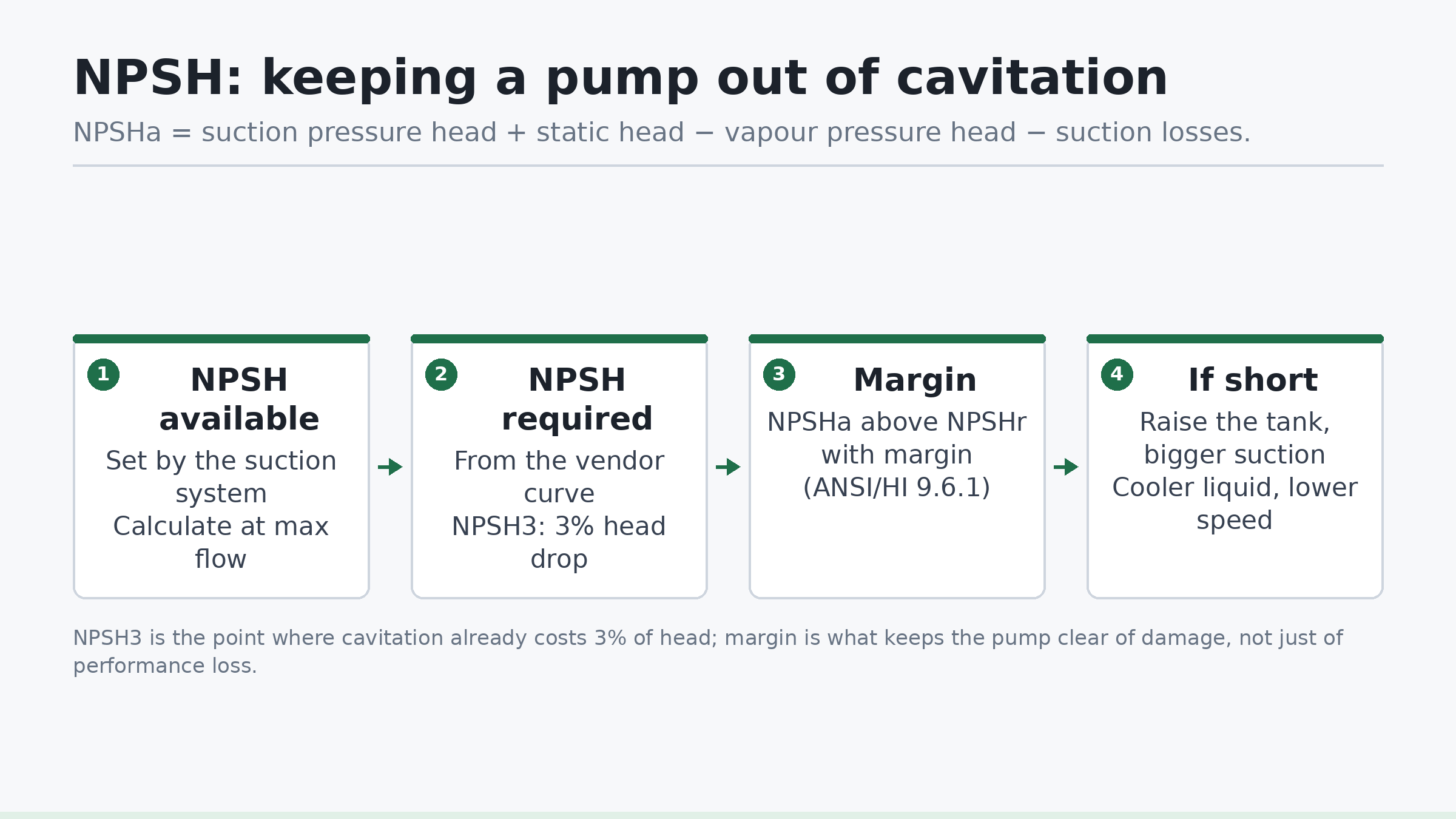
Net Positive Suction Head Available (NPSHa) is a characteristic solely of the piping layout, fluid properties, upstream vessel elevation, and operating pressure. It represents the actual hydraulic energy delivered to the suction flange. Crucially, the suction system designer has direct control over NPSHa. Because friction losses vary quadratically with fluid velocity, you must always calculate NPSHa at the absolute maximum expected operating flow rate, not merely at normal design throughput.
Net Positive Suction Head Required (NPSHr) is an intrinsic mechanical and hydraulic property of the pump impeller, eye geometry, and casing design. It is established exclusively by empirical factory performance testing under controlled conditions. NPSHr defines the minimum hydraulic head required at the suction port to prevent a predefined loss in performance.
The standard criterion for defining NPSHr in global pump test codes—such as ISO 9906:2012 (Rotodynamic pumps — Hydraulic performance acceptance tests) and ANSI/HI 14.6:2016—is designated as NPSH3. NPSH3 represents the suction head at which the first-stage discharge total head drops by exactly 3% at a constant rotational speed and constant flow rate due to vapour bubble accumulation in the vane passages. NPSH3 is not the onset of cavitation; it is the point where cavitation has advanced so far that it already degrades head by 3%. Incipient cavitation—the initial formation of microscopic vapour bubbles—frequently begins at an NPSH value two to five times higher than NPSH3. Consequently, operating a pump where NPSHa equals NPSHr guarantees continuous, low-intensity cavitation that will shorten the operating life of carbon-steel, bronze, or cast-iron components.
How to Perform an NPSH Calculation for Any Pumping System
The fundamental equation for determining Net Positive Suction Head Available is governed by the conservation of mechanical energy between the liquid surface in the suction source vessel and the pump suction centerline reference datum:
NPSHa = hp + hz − hvp − hf
Where every term is expressed as an equivalent column height of the process liquid in metres (m) or feet (ft):
- hp (Absolute Surface Pressure Head): The absolute pressure acting on the free liquid surface inside the supply tank or suction vessel, divided by the specific weight of the fluid at operating temperature. For a vessel open to the atmosphere, this is local atmospheric pressure. For a pressurized accumulator or vacuum deaerator, it is the vessel operating pressure converted to absolute units:
hp = Pabs / (ρ · g)
where Pabs is absolute pressure in Pa, ρ is fluid density in kg/m3, and g is standard gravitational acceleration (9.80665 m/s2). - hz (Static Liquid Elevation Head): The vertical distance between the minimum design liquid level in the suction source vessel and the pump centerline datum. For horizontal rotodynamic pumps, this datum is the shaft centerline. For vertical in-line pumps, it is typically the center of the suction nozzle. If the liquid surface is higher than the pump centerline (flooded suction), hz is positive (+). If the pump draws from a sump below its centerline (suction lift condition), hz is negative (−).
- hvp (Fluid Vapour Pressure Head): The absolute saturation vapour pressure of the process liquid at its maximum operating temperature, converted to equivalent liquid head:
hvp = Pv / (ρ · g)
Vapour pressure increases nonlinearly with temperature. An increase of just 5 °C in hot hydrocarbon or boiler feedwater systems can elevate vapour pressure enough to consume several metres of available head. - hf (Suction Line Friction and Dynamic Head Losses): The cumulative irreversible energy losses caused by fluid wall shear and turbulent dissipation as the process fluid flows through the suction piping, isolation valves, check valves, elbows, reducers, and suction strainers at maximum flow. This is calculated using the Darcy-Weisbach equation combined with local resistance coefficients:
hf = [ f · (L / D) + ΣK ] · [ v2 / (2 · g) ]
Where f is the Darcy friction factor, L is the straight pipe length (m), D is internal pipe diameter (m), ΣK is the sum of minor loss coefficients, and v is mean flow velocity (m/s).
Worked Engineering Example: Boiler Condensate Transfer Pump
To demonstrate the execution of a professional npsh calculation, consider an industrial condensate return system. Condensate is drawn from an atmospheric vented receiver vessel and pumped to an elevated deaerator. The system parameters are defined as follows:
- Fluid: Deconditioned water at maximum operating temperature T = 85 °C.
- Density (ρ): 968.6 kg/m3 at 85 °C.
- Atmospheric pressure (Patm): 101.325 kPa absolute (sea-level design).
- Saturation vapour pressure (Pv): 57.83 kPa absolute at 85 °C.
- Minimum static liquid level: 3.20 m above the horizontal pump centerline (flooded suction, hz = +3.20 m).
- Design flow rate (Qmax): 45.0 m3/h (0.0125 m3/s).
- Suction line geometry: Carbon steel pipe, DN100 (4-inch Schedule 40, internal diameter D = 102.3 mm = 0.1023 m; internal flow area A = 0.00822 m2; surface roughness ε = 0.045 mm).
- Piping route: 8.5 m total straight pipe length; components include 1 flanged entrance from tank (K = 0.50), 1 full-port ball valve (K = 0.05), 2 long-radius 90° elbows (K = 0.20 each), 1 eccentric reducer (K = 0.15), and 1 clean basket strainer (K = 1.20).
Step 1: Calculate Surface Pressure Head (hp)
The tank is vented to atmosphere, meaning absolute pressure equals atmospheric pressure:
hp = 101,325 Pa / (968.6 kg/m3 · 9.80665 m/s2) = 101,325 / 9,498.7 = 10.667 m
Step 2: Calculate Vapour Pressure Head (hvp)
At 85 °C, water exerts significant vapour pressure:
hvp = 57,830 Pa / (968.6 kg/m3 · 9.80665 m/s2) = 57,830 / 9,498.7 = 6.088 m
Step 3: Calculate Fluid Velocity and Friction Losses (hf)
First, calculate line velocity v:
v = Q / A = 0.0125 m3/s / 0.00822 m2 = 1.521 m/s
Velocity head: v2 / (2 · g) = (1.521)2 / (2 · 9.80665) = 2.313 / 19.6133 = 0.118 m
Compute kinematic viscosity for water at 85 °C: ν ≈ 0.339 × 10⁻⁶ m2/s. The Reynolds number (Re) is:
Re = (v · D) / ν = (1.521 · 0.1023) / (0.339 × 10⁻⁶) = 459,000 (turbulent flow)
Relative roughness: ε / D = 0.045 mm / 102.3 mm = 0.00044. Using the Swamee-Jain equation, the Darcy friction factor f ≈ 0.0182.
Summing mechanical minor loss coefficients:
ΣK = 0.50 (entrance) + 0.05 (valve) + 2(0.20) (elbows) + 0.15 (reducer) + 1.20 (strainer) = 2.30
Pipe friction loss coefficient: f · (L / D) = 0.0182 · (8.5 / 0.1023) = 1.512
Total resistance coefficient: Ktotal = 2.30 + 1.512 = 3.812
Total suction dynamic head loss:
hf = Ktotal · [ v2 / (2 · g) ] = 3.812 · 0.118 m = 0.450 m
Step 4: Calculate Total NPSHa
Substitute all values into the primary governing relation:
NPSHa = hp + hz − hvp − hf
NPSHa = 10.667 m + 3.200 m − 6.088 m − 0.450 m = 7.329 m
If the vendor pump performance curve for this duty indicates an NPSH3 of 4.80 m at 45.0 m3/h, the absolute engineering margin is:
Margin = NPSHa − NPSHr = 7.329 m − 4.800 m = 2.529 m (Margin Ratio = 7.329 / 4.800 = 1.53)
NPSH Margin Guidelines: Industry Standards
A positive difference between NPSHa and NPSHr is mandatory, but simply maintaining NPSHa > NPSHr is insufficient for long-term mechanical reliability. Process fluctuations, transient liquid levels, strainer blinding, and internal turbulence mean an intentional margin must be enforced.
The standard reference for establishing suction margins across rotodynamic pumps is ANSI/HI 9.6.1 (Rotary and Centrifugal Pumps Guideline for NPSH Margin). In critical process sectors, API 610 12th Edition (Centrifugal Pumps for Petroleum, Petrochemical and Natural Gas Industries) defines strict margins for continuous-duty turbomachinery.
Pump cavitation severity depends heavily on the liquid being handled. Pure water releases substantial acoustic and mechanical energy upon bubble collapse because it is a single-component fluid with high latent heat and high surface tension. Conversely, multi-component hydrocarbon mixtures (such as crude oils or liquefied petroleum gases) boil across a range of bubble points. When hydrocarbon micro-bubbles collapse, vaporization happens progressively rather than instantaneously, buffering the shockwave via thermal suppression (the “hydrocarbon correction factor”). Therefore, hydrocarbons can operate reliably with smaller NPSH margins than cold or medium-temperature water.
| Application / Service Classification | Governing Standard | Recommended Margin Ratio (NPSHa / NPSH3) | Minimum Absolute Margin (m) |
|---|---|---|---|
| General Industrial Water (low energy, < 75 kW) | ANSI/HI 9.6.1 | 1.10 to 1.20 | 0.6 m to 1.0 m |
| High-Energy Boiler Feedwater (> 100 °C) | ANSI/HI 9.6.1 | 1.50 to 2.00 | 1.5 m to 3.0 m |
| Refinery Hydrocarbons (API 610 Service) | API 610 12th Ed. | 1.10 minimum | 1.0 m (or 10% of NPSH3, whichever is greater) |
| Chemical Process (corrosive, toxic liquids) | ISO 5199 / ANSI/HI | 1.25 to 1.40 | 1.0 m to 1.5 m |
| Cooling Tower Circulation | ANSI/HI 9.6.1 | 1.20 to 1.30 | 1.0 m to 1.2 m |
When selecting a margin, engineers must also consider Suction Specific Speed (Nss), defined as:
Nss = [ N · (Q)0.5 ] / (NPSH3)0.75
Where N is speed in RPM, Q is BEP flow rate in m3/s, and NPSH3 is in metres. Impellers engineered with high suction specific speed (Nss > 11,000 to 12,000 in metric units) have enlarged impeller eyes designed to achieve artificially low NPSHr. However, these aggressive geometries narrow the stable operating window, inducing suction recirculation, severe low-flow cavitation, and axial surging when operating away from the Best Efficiency Point (BEP). For high Nss pumps, maintaining an elevated margin ratio is vital across the entire allowable operating region.
Troubleshooting: What to Do When NPSHa is Insufficient
If your calculation indicates that NPSHa does not satisfy the required margin above NPSHr, modify the hydraulic system before procuring equipment or pouring foundations. The primary levers fall into two categories: suction side modifications (raising NPSHa) and machine selection adjustments (reducing NPSHr).
1. Elevate the Liquid Source
Raising the physical elevation of the supply tank, deaerator, or separator drum directly increases the static head term (hz). In industrial plant layouts, vessels such as deaerators are placed on elevated piperacks 6 to 12 metres above ground level specifically to supply sufficient positive static head to boiler feedwater pumps operating near liquid boiling temperatures.
2. Increase Suction Pipe Diameter
Because dynamic frictional losses vary inversely with the fifth power of pipe diameter for a given volumetric flow rate (hf ∝ 1 / D5), increasing suction line size provides substantial gains. Standard piping practice dictates sizing suction lines one to two nominal pipe sizes larger than the pump suction nozzle. Suction liquid velocities should generally be kept within conservative bounds:
- Boiling or saturated liquids: 0.6 m/s to 1.2 m/s
- General industrial process water: 1.0 m/s to 1.8 m/s
- Light hydrocarbons: 0.8 m/s to 1.5 m/s
3. Lower Fluid Operating Temperature
Vapour pressure is an exponential function of temperature. If the thermal process allows, introducing an upstream suction heat exchanger or subcooler drops Pv substantially, instantly regaining available head. A drop of only 3 °C to 5 °C in hot condensate systems can yield a 1.0 to 2.5-metre increase in NPSHa.
4. Select a Lower-Speed Pump or Multi-Suction Impeller
Rotational speed has a dominant effect on pump suction requirements. NPSHr scales approximately with the square of pump rotational speed (NPSHr ∝ N2). Selecting a 4-pole motor (approx. 1,450 RPM at 50 Hz or 1,750 RPM at 60 Hz) instead of a 2-pole motor (approx. 2,900 / 3,500 RPM) drastically slashes NPSHr, often by more than 60%, albeit requiring a physically larger pump casing.
Alternatively, specifying a double-suction impeller design splits the volumetric flow equally across two back-to-back impeller eyes. Because each inlet processes only Q / 2, the fluid approach velocity is significantly lower, reducing NPSHr by approximately 25% to 35% compared to an equivalent single-suction machine.
5. Install an Impeller Inducer
When civil layout, vessel elevation, and operating speed cannot be changed, consider equipping the centrifugal pump with an inducer. An inducer is an axial-flow helical screw mounted directly onto the pump shaft immediately upstream of the centrifugal impeller eye. It adds a modest pressure head rise (typically 1.5 to 4.0 m) under low-NPSH conditions without cavitating destructively, satisfying the suction head demands of the primary impeller. Note that inducers narrow the pump’s allowable operating window and can create low-flow instability if operated far back from BEP.
Checklist for Engineers
- Calculate at Absolute Maximum Flow: Never calculate NPSHa using nominal or average flow rates; always calculate at the extreme pump run-out condition where velocity and friction losses peak.
- Evaluate Minimum Liquid Level: Base the static elevation head (hz) strictly on the lowest operational liquid level (e.g., Low-Liquid Level Trip point) inside the supply vessel, not the normal liquid level.
- Convert All Pressures to Absolute Values: Verify that surface vessel pressure (hp) and liquid vapour pressure (hvp) are converted to true absolute terms before subtracting. Mixing gauge pressure with absolute values is the most common mathematical error in suction design.
- Account for Suction Strainer Loading: Size suction line head loss using a partially blinded strainer condition (typically assumed at 50% open area blockage) rather than clean-mesh vendor specifications.
- Check Off-BEP Operation: Consult vendor performance curves across the full operating spectrum. NPSHr increases sharply as the operating point drifts toward high-flow run-out, but can also rise under low flows due to suction recirculation.
- Verify Suction Line Geometry: Confirm the suction piping includes a minimum straight run of 5 to 10 pipe diameters directly upstream of the pump suction flange to prevent uneven velocity profiles and flow pre-rotation at the impeller eye.
- Apply the Appropriate Margin Standard: Ensure the final margin adheres to ANSI/HI 9.6.1 or API 610 requirements based on fluid service, liquid temperature, and operating criticalities.
Frequently Asked Questions
What is the difference between NPSHa and NPSHr?
NPSHa (available) is the absolute total suction head provided by the upstream process system, suction vessel elevation, and piping layout. It is calculated by the piping engineer. NPSHr (required) is the minimum total suction head the pump requires at its suction flange to maintain stable performance, established exclusively by the equipment manufacturer through standardized hydraulic factory testing.
Why does pump cavitation cause noise that sounds like pumping gravel?
The characteristic rattling noise is generated by the micro-implosion of millions of vapour cavities per second. When bubbles formed in the low-pressure suction eye sweep into the high-pressure regions between the impeller vanes, the surrounding fluid rushes inward symmetrically. The final stage of collapse creates shockwaves with localized pressures exceeding 1,000 MPa, striking metal surfaces at supersonic speeds and ringing the pump casing acoustically like small gravel stones.
Does a pump operate safely if NPSHa exactly equals NPSHr?
No. Standard manufacturer curves define NPSHr as NPSH3, the condition where cavitation has already caused a 3% drop in total discharge head. At this threshold, cavitation is already active, eroding impeller surfaces and causing mechanical vibration that reduces mechanical seal and bearing life. Operating with NPSHa equal to NPSHr provides zero margin for operational transients or line fouling.
How does liquid temperature affect the NPSH calculation?
Liquid temperature impacts the calculation through saturation vapour pressure and liquid density. Vapour pressure rises nonlinearly as temperature increases. For instance, water at 20 °C has a vapour pressure of 2.34 kPa absolute (0.24 m head), while water at 95 °C exerts 84.53 kPa absolute (8.96 m head). This thermal effect consumes over 8.7 metres of available head, requiring pressurized suction tanks or significantly elevated source vessels.
For complex pump system design, transient hydraulic modeling, or green hydrogen balance-of-plant fluid systems, contact Avoltium to collaborate with an experienced engineering team.