
When engineering teams visit our testing facility at Avoltium, they usually head straight for the massive titanium end plates, high-current rectifiers, and cell stack compression rigs. They want to talk about high current densities and gas-liquid separators. But when I ask about their feed water conditioning setup, I often get hand-waving answers about standard city water or basic demineralizers.
That is a massive mistake.
In actual plant operations, the commercial success of a hydrogen facility rarely hinges on the stack dynamic response alone; it lives or dies by the quality of the water hitting the catalyst layer. If your feed stream carries even fractional parts-per-billion (ppb) levels of metal ions or dissolved silica, your high-tech stack turns into an expensive ion trap.
Operational Reality: Why Upstream Water Treatment Dictates Stack Lifespan
Every commercial Electrolyzer requires feedwater conditioned to ultra-pure standards—typically ASTM Type I or II with an electrical resistivity exceeding 18.2 MΩ·cm. When water quality falls below this threshold, dissolved contaminants instantly start competing with catalytic sites.
Divalent and trivalent cations such as Ca2+, Mg2+, and Fe3+ possess a higher affinity for sulfonic acid functional groups within proton exchange membranes than native H+ ions. As these heavy ions accumulate in the polymer matrix, they displace charge-carrying protons, causing an exponential increase in membrane ionic resistance.
“If you feed an electrolyzer municipal tap water, you aren’t just shortening its operating life; you are actively paying electrical utilities extra money to burn out your catalyst beds.”
Meanwhile, an unfiltered Water Treatment system letting micro-silica through will cause immediate scaling on the porous transport layers (PTLs). This fouling blocks gas evacuation channels, trapping oxygen bubbles against the anode catalyst layer and creating localized thermal hotspots that burn right through the solid polymer electrolyte.
Technical & Operational Schematic Analysis
In a proton exchange membrane (PEM) cell, deionized feed water enters the anode channel where the Oxygen Evolution Reaction (OER) oxidizes H2O into O2 gas, protons (H+), and electrons over an IrO2 catalyst bed. Hydrated protons migrate across the perfluorosulfonic acid membrane toward the cathode under an applied electric field, while electrons travel through the external circuit. At the cathode catalyst layer, the Hydrogen Evolution Reaction (HER) reduces H+ ions over platinum nanoparticles to yield high-purity H2 gas. Any trace ionic impurities like Ca2+ or Fe3+ in the feed water foul the active catalyst sites and cause rapid ionic resistance spikes across the membrane.
Deconstructing Stack Overpotential and Energy Balance
To understand what fouling does to your operating expenses, look closely at the thermodynamic voltage breakdown of a cell under load. The voltage you supply to an active stack is always higher than the ideal reversible potential due to irreversible voltage losses, known as overpotentials.
| Symbol | Description | SI Unit |
|---|---|---|
| Vcell | Total Operating Cell Voltage | V (Volts) |
| Erev | Reversible Cell Potential (Thermodynamic Minimum, ~1.23V at standard state) | V (Volts) |
| ηanode | Anode Activation Overpotential (Oxygen Evolution Reaction) | V (Volts) |
| ηcathode | Cathode Activation Overpotential (Hydrogen Evolution Reaction) | V (Volts) |
| I | Operating Current Density | A/cm² (Amperes per square centimeter) |
| Rinternal | Area Specific Ohmic Resistance (Membrane, PTL, and contact interfaces) | Ω·cm² (Ohm-square centimeters) |
When water feed quality slips, the term hit worst is Rinternal. Ionic contamination directly reduces proton mobility across the polymer backbone, sending Rinternal through the roof. If cell resistance rises by even 20 mΩ·cm², operating at 2 A/cm² inflates cell potential by 40 mV.
Multiply that 40 mV bump across a 100-cell commercial stack operating at 1,500 Amperes, and you are suddenly dumping an extra 60 kW of waste heat into your cooling loop every single hour. What this means for your capital expenditure is straightforward: either you spend money on proper pre-treatment filters upfront, or you pay the power utility for wasteful resistive heat generation until the stack fails outright.
Practical Balance of Plant Design for Field Engineers
Building a robust multi-stage pre-treatment system isn’t over-engineering; it’s basic risk management for plant operators. At Avoltium, we enforce a strict multi-tier pre-treatment train before raw process water ever meets the stack input manifold.
“High-purity process water isn’t an option or an upgrade package—it is a core mechanical requirement for electrochemical plant reliability.”
Here is the baseline flow standard we mandate in field operations:
- Mechanical Filtration: Multi-media media beds followed by 1-micron cartridge filters to strip out suspended solids, silt, and macro-particulates.
- Reverse Osmosis (RO): Two-pass RO skid to drop total dissolved solids (TDS) by over 98%, taking raw conductivity down to micro-Siemens territory.
- Electrodeionization (EDI): Continuous EDI units that use applied voltage to constantly pull trace ions out of the water stream without needing chemical regeneration shutdowns.
- Polishing Mixed Bed Deionizers: Final nuclear-grade ion-exchange resin beds placed right before the stack inlet to catch any remaining ionic slip and guarantee a continuous resistivity of 18.2 MΩ·cm at 25 °C.
Integrating a continuously monitored Water Treatment skid with online resistivity sensors and automated divert valves ensures that if water quality ever dips below target parameters, flow drops out before bad water reaches the active stack components.
Final Takeaways for Project Execution
Don’t fall into the trap of assuming that off-the-shelf equipment handles field variations without tweaking. Test your source water chemistry across all four seasons, budget appropriately for replacement RO membranes, and monitor stack loop conductivity like a hawk.
Treat your incoming feed stream with the same engineering rigor as your high-voltage power distribution, and your modern Electrolyzer stack will hit its full 80,000-hour design life without unforced operational failures.
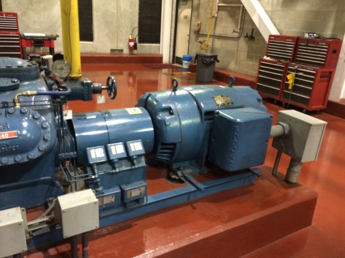
Image: Reciprocating Compressor from an Industrial Refrigeration System by Endora6398, licensed under CC BY-SA 4.0.